background image

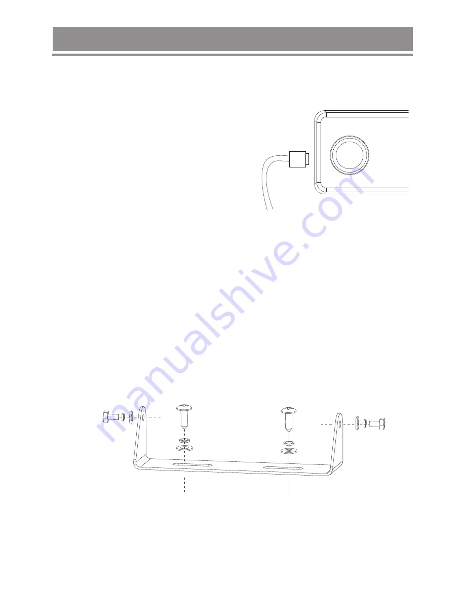
Mounting the Cradle

Connecting the Microphone

The microphone uses a miniature 6 pin style plug 
and socket.
To connect the microphone:

1. Push the MIC plug at the end of  the 

microphone cord into the MIC jack until the 
connection locks into place. 

Gently tug the MIC cord to test that the 

connection is locked.

2. Use the MIC Jack cover which is threaded 

onto the MIC cord to seal the MIC jack entry 
from dust.

The cradle can be screwed or bolted in any convenient location in your vehicle (under 
or above the dash, on the centre console, etc) using the mounting slots provided in the 
base. 

For maximum sound output from the build in speaker, we recommend the cradle be 
mounted above the radio to minimize any obstruction of the speaker.

Avoid mounting close to heaters or air conditioners. Screw the mounting cradle to a 
firm surface and put the radio into the cradle from the front until it clicks into place.

Finally, connect the power cord and antenna cable to the sockets provided at the rear 
of the radio.

Installation

-6-

Summary of Contents for DC-1122

Page 1: ...Compact 5W UHF CB Radio Instruction Manual DC 1122 ...

Page 2: ......

Page 3: ...nsmission Frequency 476 4250MHz 477 4125MHz 80 channels 5W output power TOT Timer 38 CTCSS and 104 DCS 100 User Programmable RX Channels Instant Priority Channel setting Busy Channel Lockout Memory store Call tone melody 10 songs Base unit rotary volume LCD back light function 3 colours orange red green Key back light 5 step adjustable and automatic squelch function Repeater function Key tone func...

Page 4: ...se front Rear view 1 MIC Jack 2 Volume knob 3 Main speaker 4 Power Input Connection 13 8VDC or 27 6VDC 5 EXT SP External Speaker Jack 6 UHF Antenna Connection Control and Indicators 2 EXT SP DC 13 8V DC 27 6V ANT 2 ...

Page 5: ...Volume Up 8 Memory Button 18 Volume Down 9 PO FI and CTCSS DCS button 19 Memory channel Select and 10 Channel Up Dual Watch Button 11 Scan Button 20 Squelch Button 12 Confirm Button 21 Power Button 13 Channel Down 22 Menu Button 14 Speaker 23 RJ45 type plug 15 INST Button 24 Jack Cover 3 SCAN MEM SQ CTCSS DCS PO FI M SEL DUAL ...

Page 6: ...ed 5 POL Police bank 16 CTCSS DCS code number 6 CB UHF CB Extra RX channel 17 Channel number bank 18 Signal Power level 7 FIRE Fire Ambulance bank 19 SCAN Scan mode 8 MON Monitor 20 BCL Busy channel lockout 9 CAP 21 CALL Call tone transmit 10 GS Goup Scan 22 TSQ Tone Squelch enabled 11 INST Instant channel 23 Channel Frequency CAP FIRE CB POL MEM RX TX REP PRI SCAN DUAL INST CALL MON GS TSQ BCL CT...

Page 7: ...F CB Radio Instruction Manual DC 1122 Included with Radio Standard Microphone Instruction manual Microphone Hanger Screws Washers Mounting cradle Screws Washers DC Power Cord 5 SCAN MEM SQ CTCSS DCS PO FI M SEL DUAL ...

Page 8: ...The cradle can be screwed or bolted in any convenient location in your vehicle under or above the dash on the centre console etc using the mounting slots provided in the base For maximum sound output from the build in speaker we recommend the cradle be mounted above the radio to minimize any obstruction of the speaker Avoid mounting close to heaters or air conditioners Screw the mounting cradle to...

Page 9: ...pply high quality Double Sided tape onto the flat area of the MIC Hanger back piece and then press firmly to the mounting position Conventional Mounting with Screws Use the front part of the MIC hanger only Locate a suitable mounting position mark and drill two 3mm holes Fix the MIC hanger into place with screws Mounting the MIC Hanger The Microphone Hanger comes in two parts How and where you mou...

Page 10: ...eds 28 8V DC an alert tone sounds and HI DC flashes for 5 seconds The power source must not exceed 32V DC otherwise permanent damage may occur to your radio which may not be covered by the manufacturer s warranty If the input voltage falls below 10 2V DC LO DC flashes for 5 seconds The power turns off automatically if voltage falls below 9 0V DC Turning your unit OFF and disconnect it from the pow...

Page 11: ...y use this repeater function when a long distance communication via the local repeater facility is specifically required Unless it is necessary avoid operation on locally used repeater input channels channels 31 38 and 71 78 or locally used repeater receiving channels channels 1 8 and 41 48 Channel 11 is the customary calling channel in Australia for establishing communication Channel 40 is the cu...

Page 12: ... or scanning The 80 UHF CB channels are numbered 01 80 The user programmable RX channels are numbered 81 180 and only show in the CTCSS DCS code area when programmed When the POL icon is showing then pre programmed police frequencies will be available When the FIRE icon is showing then pre programmed fire ambulance frequencies do not have channel numbers instead PO appears in the channel display f...

Page 13: ...pear While holding the PTT button speak into the microphone using a normal tone of voice Hold the microphone in a vertical position about 5 to 7 cm from the mouth PTT CALL INST Programming the Instant Priority Channel Press 5 or 6 button to select the Priority Channel you prefer Press and hold INST button to store the new setting INST icon appears Momentarily press INST to return to the Instant ch...

Page 14: ... has 104 DCS private codes available Different DCS tones may be associated to different channels DCS codes follow after the 38 CTCSS codes Follow the steps for setting a CTCSS code Press 5 or 6 button until the DCS codes flashes Press CTCSS DCS to store the new setting NOTE Selecting a CTCSS DCS code will disable the CTCSS DCS feature To communicate between two or more units both the channel and C...

Page 15: ...f weak signals High noise areas may still break the squelch Dual Watch setting Dual Watch will continuously monitor the Instant channel and the current channel for activity Press and hold DW button until DUAL icon appears or disappears NOTE Every 1 5 seconds the Instant channel is monitored for 100m sec Dual watch function stops temporarily when receiving a signal Dual watch function is invalid in...

Page 16: ...s your signal and retransmits on Ch01 Operating the UHF CB Radio in Duplex Mode Press MENU button once the duplex icon flashes Press 5 6 to change the setting between ON or OFF standard channel numbering REP icon appears when a selected channel is set to Duplex mode NOTE Only channels 01 08 and channels 41 48 are available for Duplex Check with your local Retailer from information on available rep...

Page 17: ...ore MEM icon appears To remove the channel from SCAN memory press and hold MEM once more The MEM icon disappears Open Scan OS Mode OS Mode is the default scan setting All UHF CB user programmed extra RX channels Police and Fire Ambulance frequencies have been added to the OS SCAN Memory for convenience Tao add remove channels from OS SCAN Memory Allows continuous scanning of all selected channels ...

Page 18: ...ning stops on a channel which is not a Priority Channel UHF CB Radio will continue monitoring the Priority Channel for activity while listing to the active one To select GS Scan Mode 1 Press MENU three times the GS setting flashes 2 Press 5 6 to change the setting between ON and OFF Call Tone setting Press MENU four times the call icon flashes Press 5 6 to change the setting between 0 to 10 Busy C...

Page 19: ...annel UHF CB channel Press and hold MENU the lowest available empty RX channel will flash Press 5 6 if you wish to select another RX channel Press SQ to begin the frequency edit The MHZ digit range flashes Use MENU to shift between MHZ range between 400 520MHz kHz range in 12 5kHz steps Press 5 6 to select the desired frequency within MHz kHz ranges When finished press SQ The channel flashes to en...

Page 20: ...476 6500 476 6750 476 7000 476 7250 476 7500 476 7750 476 8000 476 8250 476 8500 476 8750 476 9000 476 9250 476 9500 476 9750 477 0000 477 0250 477 0500 477 0750 477 1000 477 1250 477 1500 477 1750 477 2000 477 2250 477 2500 477 2750 477 3000 477 3250 477 3500 477 3750 477 4000 476 4375 476 4625 476 4875 476 5125 476 5375 476 5625 476 5875 476 6125 476 6375 476 6625 476 6875 476 7125 476 7375 476 ...

Page 21: ...s Speech telephony is inhibited on Channel 22 and 23 Channel 1 8 and 31 38 41 48 and 71 78 are used as repeater channels with 750kHz offset Channels 1 8 and 41 48 are used for mobile reception and channels 31 38 and 71 78 for mobile transmission Only use this repeater function when a long distance communication via the local repeater facility is specifically required Unless it is necessary to avoi...

Page 22: ...114 115 116 122 125 131 132 134 143 145 152 155 156 162 165 172 174 205 212 445 446 452 454 455 462 464 465 466 503 506 516 523 526 532 546 565 606 612 624 627 631 632 654 662 664 703 712 723 731 732 734 743 754 223 225 226 243 244 245 246 251 252 255 261 263 265 266 271 274 306 311 315 325 331 332 343 346 351 356 364 365 371 411 412 413 423 431 432 36 37 38 39 40 41 42 43 44 45 46 47 48 49 50 51 ...

Reviews: