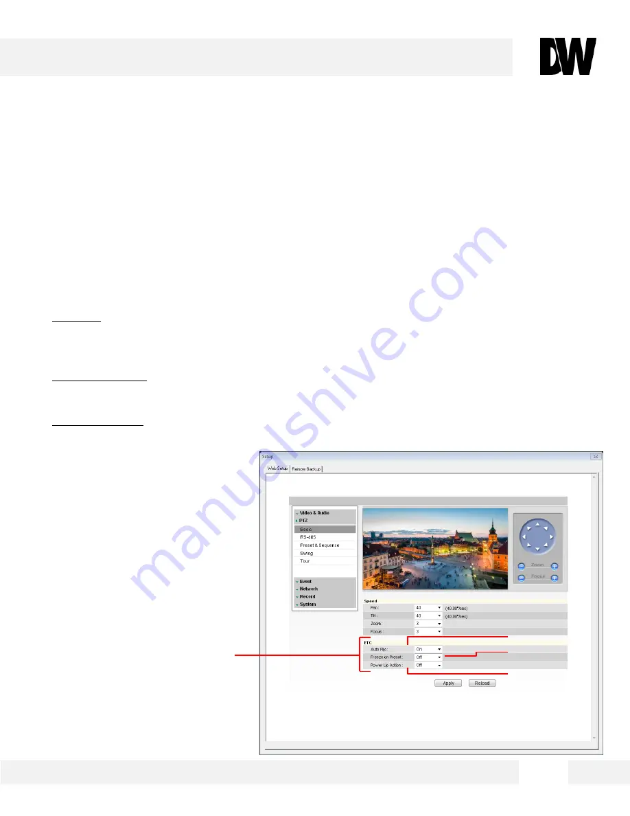
background image

WEBVIEWER* 

5 1  

[Etc. Settings] 

[5] 
[6] 

[7] 

S e t u p  >   P T Z >  B a s i c  

 
U s e   t h e   M P T Z 2 0 X ’ s   P T Z   b a s i c   s e t t i n g s   m e n u   t o   a d j u s t   t h e   f e a t u r e s  
r e l a t e d   t o   t h e   c a m e r a ’ s   s p e e d ,   h o m e   a c t i o n   a n d   z o o m   a n d   f o c u s .  


E T C  

5. Auto Flip- When the tilt angle arrives to the top of tilt orbit (90

°), zoom module camera continues 

moving opposite of the tilt direction (180

°) to continue tracing targets. If Auto Flip is enabled, when 

the zoom module camera passes through the top of the tilt direction (90

°), images should be 

reversed automatically. Default is ON.  

6. Freeze on Preset- If  enabled, the camera will freeze on a preset rather than who live image. If 

Freeze on Preset is on while a tour is on, user will not see the camera’s movement, only the 
presets during dwell time. Default if OFF. 

7. Power Up Action- If power up action is set to be on, camera will continue the function which is 

executed lastly after rebooting. Default is OFF.  


Summary of Contents for MEGApix DWC-MPTZ20X

Page 1: ...ing the camera please read and follow this manual carefully Before installing or operating the camera please read and follow this manual carefully 11202013 DWC MPTZ20X DWC MPTZ20XFM Flush Mount Model IP 2 1MP Pan Tilt Zoom Camera ...

Page 2: ... the temperature may rise to high levels Cleaning To remove dirt from the case moisten a soft cloth with a soft detergent solution and wipe Mounting Surface The material of the mounting surface must be strong enough to support the camera This equipment has been tested and found to comply with the limits for a Class B digital device pursuant to Part 15 of the FCC rules These limits are designed to ...

Page 3: ...ding Cameras using the IP Finder Software 30 Camera Reboot 31 MEGAPIX Camera Web Viewer 32 Accessing the Web Viewer via Internet Explorer 32 Accessing the Web Viewer via Google Chrome Mozilla Firefox and Safari 33 GUI Description 34 First Second Stream 35 Export Image 36 Print Image 37 Instant Recording 38 39 Controlling the Camera using Virtual Joystick 40 41 MEGAPIX Camera Setup 42 Video 42 49 P...

Page 4: ...Second Pan Speed Vector Drive Technology Pan Tilt Motion in Shortest Path 255 Preset Positions 4 Patterns 8 Swings 8 Groups WDR Wide Dynamic Range 3D DNR 3D Digital Noise Reduction Two Way Audio 3 Sensor Inputs 1 Sensor Output Motion Detection with Smart Notifications Micro SD SDHC Class 10 Card for Emergency Backup IP66 Certified Weatherproof MPTZ20X Only Flush Mount Housing MPTZ20XFM Only Heater...

Page 5: ...1 Mounting Bracket Wall and Ceiling options available 2 Housing Safety Wire Hanger 3 Sun Shield Upper Housing 4 Camera Module 5 Dome Safety Wire 6 Camera Dome PARTS DESCRIPTIONS MPTZ20X 5 ...

Page 6: ...ide Connectors 3 Cover Dome 4 Camera Module 5 Camera Hooks 6 In Ceiling Housing 7 Camera Module Hook Guide 8 Mounting Clip Bolt 9 Mounting Clip 10 Housing Safety Wire Hanger 11 Flush Mount Hook 12 Flush Mount 13 Flush Mount Cover Side Connectors 14 Flush Mount Cover ...

Page 7: ...an Defrosts the dome cover and removes moisture 4 Heater Defrosts the dome in low temperature by increasing the internal temperature of the camera housing 5 Audio Output Port Connection for audio output cables 6 Audio Input Port Connection for audio input cables 7 Micro SD Card Slot Enter a micro SD card for local emergency backup not included 8 Power Port Connect 24VAC power source ...

Page 8: ...DIMENSIOSN MPTZ20X 8 ...

Page 9: ...DIMENSIOSN MPTZ20XFM 9 ...

Page 10: ... camera 1 Housing Safety 2 Water Proof Tape 3 Hexagonal Wrench 4 Anchor Bolt 4pcs 5 Hole Template 6 CD Manual QSG IP Finder Software 7 Safety Wire 8 Quick Start Guide QSG 1 Wall Mount Camera Type 2 Ceiling Mount Camera Type INSIDE THE BOX MPTZ20X 1 0 ...

Page 11: ...INSIDE THE BOX MPTZ20XFM 1 1 1 Dome Cover 2 Camera Module in Flush Mount Housing 3 2x Safety Wires 4 Quick Start Guide QSG 5 CD Manual QSG IP Finder Software ...

Page 12: ...led Switch The MEGAPIX Camera is PoE compliant allowing transmission of power and data via a single Ethernet cable connected to a PoE injector PoE injectors eliminates the need for the different cables used to power record or control the camera Follow the illustrations below to connect the camera to a PoE injector using an Ethernet cable 2 Using 24VAC If a PoE injector is not available use a power...

Page 13: ...ts Note the Anchor bolts included in with the camera kit are for concrete Be sure to consult with your installer what bolts are necessary depending on the wall ceiling surface 4 Using a drill drill four 4 holes for the bolts Mount the Mounting box on the wall ceiling Note If your camera model includes the inner box inside the Mounting Box make sure the cables remain intact during installation INST...

Page 14: ...hold both black handles on the camera mechanism Pull them up to detach the camera 7 Remove the tape used to fix the PTZ mechanism after detaching the PTZ mechanism from the upper housing This was used to protect the camera s lens during shipping and should be removed before turning the camera s power on INSTALLATION 1 4 5 6 7 ...

Page 15: ... proof tape on the pipe of the upper housing 9 Hook the safety cable between the mounting accessory and the upper housing 10 Attach the upper housing to the mounting pole by rotating it clockwise until the upper housing and the mounting accessory are tightly connected 10 INSTALLATION 1 5 ...

Page 16: ...diagram below for more information a Alarm In Out Port b Audio In Port c Audio Out Port d Network Cable Port e Power Port f Micro SD Card Slot Cover 13 Check the LED lights are on Green light flickers when the camera is booting and Red light turns on when booting is complete See next page for proper cabling connections and SD Card installation INSTALLATION 1 6 ...

Page 17: ...INSTALLATION 1 7 Cabling U s e t h e d i a g r a m b e l o w f o r p r o p e r c a b l i n g o f p e r i p h e r a l d e v i c e s s u c h a s 2 n d v i d e o o u t p u t p o w e r a n d n e t w o r k ...

Page 18: ...LATION 1 8 Cabling U s e t h e d i a g r a m b e l o w f o r p r o p e r c a b l i n g o f p e r i p h e r a l d e v i c e s s u c h a s 2 n d v i d e o o u t p u t a l a r m s i n p u t s a n d o u t p u t s ...

Page 19: ...N 1 9 Cabling U s e t h e d i a g r a m b e l o w f o r p r o p e r c a b l i n g o f p e r i p h e r a l d e v i c e s s u c h a s a u d i o i n p u t m i c r o p h o n e a n d a u d i o o u t p u t s p e a k e r ...

Page 20: ...S D C a r d f o r l o c a l e m e r g e n c y b a c k u p W h e n s e t u p p r o p e r l y t h e c a m e r a w i l l r e c o r d t o t h e l o c a l S D c a r d w h e n i t d e t e c t s i t i s n o t r e c o r d i n g t o a n y s e r v e r s a n d i s n o t c o n n e c t e d t o t h e n e t w o r k ...

Page 21: ...using press the two black handles until the module makes a clicking sound 16 Close the dome cover Care must be taken to place the dome cover on the camera housing by matching the Arrow Mark 17 Tighten the four screws on the dome cover in sequence as shown in the picture NOTE To achieve optimal sealing the torque of each screw must be in the range between 0 5 1 0 N m 0 3 0 73 lbf ft 14 15 16 17 ...

Page 22: ...oth black handles on the camera mechanism Pull them up to detach the camera 2 Detach the Flush Mount cover by pressing on the connectors on the side of the flush mount housing 3 To mount the flush mount camera in the ceiling drill a 190mm 7 48 diameter hole in the ceiling 4 Use the safety wires to secure the flush mount to the ceiling during and after installation ...

Page 23: ...plicable port Use the diagram below for more information a Alarm In Out Port b Audio In Port c Audio Out Port d Network Cable Port e Power Port f Micro SD Card Slot Cover 7 Check the LED lights are on Green light flickers when the camera is booting and Red light turns on when booting is complete See pages 17 20 for proper cabling connections and SD Card installation ...

Page 24: ...se the Flush Mount cover by attaching the connectors to the side of the flush mount 9 Insert the in ceiling housing into the ceiling hole and press the edge of the housing against the ceiling 10 Secure the in ceiling housing in place by turning the clip bolts located on the housing Clockwise ...

Page 25: ... mechanism to the upper housing press the two black handles until the module makes a clicking sound 13 Close the dome cover dome and secure it to place using the accessory wrench 14 When the installation is complete remove the protective plastic from the cover dome To remove the camera from the in ceiling installation use a flat head or a coin to snap the flush mount housing out ...

Page 26: ...ocal network The software can be found on the included User Manual CD Run IP Finder and install onto your PC 2 When setup is complete launch IP Finder 3 To find your MEGAPIX camera click Search button Your MEGAPIX camera will appear as DWC MPTZ20X 4 Select the desired device and click Web Connect to access the camera directly via Internet Explorer Install the IP Finder to a computer located on the...

Page 27: ... c a m e r a 1 Configuration Change the device s connection type and or IP address information Please see the next page for further explanation 2 Upgrade Upgrade the device s firmware 3 Timezone Change the timezone 4 Import Config Import setup configuration for a specific device 5 Web Connect Connect to the MEGAPIX camera through Internet Explorer IP FINDER SOFTWARE 5 4 3 2 1 2 7 ...

Page 28: ...nd password 3 Static IP Select Static to connect to the camera from an external network For further explanation on Static please see PAGE 29 4 Use DDNS Check this option to use DDNS service For further explanation on DDNS please see PAGE 29 5 Port The port numbers required for communication with the camera Use the IP Finder to change other basic settings for your MEGAPIX camera The menu options ma...

Page 29: ...mmend that you 1 setup the camera to DHCP 2 allow it to configure itself according to your network and 3 change the settings to a static IP address 1 To set your MEGAPIX camera to Static highlight the desired device from the search results list and click on Configuration In the Network Configuration window make sure Static is selected 2 Enter the following information IP Address Netmask Gateway an...

Page 30: ... The system will start updating all the selected cameras in a new window 5 The system will indicate if the upgrade was successful or not for each camera 6 When all cameras have been properly upgraded press the Close button 7 To complete the upgrade reboot the cameras by pressing the server reboot button 8 Press the Exit 9 Allow up to 60 seconds for the cameras to reboot and press the Search button...

Page 31: ...a u l t P r e v i o u s s e t u p f o r I P d e f a u l t t i m e e t c w i l l b e d e l e t e d I f a s y s t e m s I P a d d r e s s i s l o s t r e s e t t h e c a m e r a b a c k t o f a c t o r y d e f a u l t The following are the default network settings CAMERA REBOOT IP Mode DHCP IP Address 192 168 1 123 Subnet Mask 255 255 255 0 Gateway 192 168 1 23 Command Port 7000 HTTP Port 80 Live Po...

Page 32: ...n w e b v i e w e r 1 Type the IP address of the camera on the Internet Explorer window Example http 192 168 1 123 Factory Default 2 Enter Username and Password Username admin Password admin 3 The web browser will ask to install ActiveX Control Once it has been installed Internet Explorer will display video images from the camera WEBVIEWER 3 2 ...

Page 33: ... 2 Enter the IP camera s IP address If the first stream is set to H 264 then a video will not be displayed on the GUI 3 Click the Setup button located at the top right of the page Then go to Video Stream Settings 4 Modify one of the two 2 streams to the codec MJPEG 5 When you are finished modifying the streams click Apply and Reload to make sure all changes have been saved and your camera has been...

Page 34: ...t Camera s Current Display Start Stop Panic Recording Show Hide PTZ Virtual Controller PTZ Virtual Controller Camera s Name Time Full Screen Mode Main Display Area Alarm Status Camera s Date Time Stream s Name Camera s IP Address Stream Control Sensor Control Relay Control 2 Way Audio Control ...

Page 35: ...c o r d i n g On the main monitoring page user can view the camera with the First Stream settings or the Second Stream settings Below the display screen click on the First Stream and Second Stream buttons to view the different camera settings To Setup Stream Settings refer to page 42 WEBVIEWER Streams Selection 3 5 ...

Page 36: ...o t o y o u r c o m p u t e r 1 Click Export Image button located on the left Save As window will appear 2 A jpg image will automatically be stored under a WNMDWViewer folder 3 The image s name will include the camera s IP address Channel name and date and time Export Image 3 6 WEBVIEWER ...

Page 37: ...e the size of the screenshot or adjust the orientation of the screenshot 3 To print the information about the screenshot select View Title To add a memo for the screenshot click Page Option 4 Go to Printer Setup to select the printer and manage the printer properties 5 Select Print to print the page or Close to cancel the print WEBVIEWER Print Image 3 7 ...

Page 38: ...ick on the Record button located to the left of the Webviewer 2 Setup where you want the videos to be saved 3 Setup the duration of the instant recording You can record up to 120 seconds of live video 4 When setup is complete click OK to save changes or Cancel to cancel any changes Local Recording 3 8 WEBVIEWER ...

Page 39: ... To Start right click anywhere on the display screen 2 Click on Start Rec The icon on the top right of the screen will change to INSTANT 3 To Stop right click anywhere on the display screen 4 Click on Stop Rec The video will be displayed in the designated folder when recording is complete WEBVIEWER Local Recording 3 9 ...

Page 40: ...ove the camera UP To stop the camera s movement release the mouse button 2 Zoom Control Button The Zoom ratio of the camera can be controlled by using the and buttons Press the to make the camera zoom into the center of the image Press to make the camera zoom out to the full field of view 3 Focus Control Button The focus of the camera can be controlled by clicking or button Please note If Focus Mo...

Page 41: ...s and swings Each tour can have a maximum of 20 action 9 Presets buttons the numeric buttons 1 10 allow you to send the camera to a specific preset previously setup Press the preset number to move the camera to that position To move the camera to a saved preset from the main viewer a Select the Preset s number from the available buttons b To activate presets higher than 10 expand the Advanced Menu...

Page 42: ...pe of compression to use when outputting the video The compression type affects the image quality bandwidth and file size of saved images MJPEG the lowest Compression type will provide the highest image quality but also will cause the image size to be the largest and take up the most bandwidth 4 Data Transfer Speed Set encoding bitrate if H 264 and MPEG4 compression type is selected 5 Frame rate S...

Page 43: ...m Auto or Manual If AUTO is selected the camera will automatically adjust itself to the proper white balance If MANUAL is selected adjust the following values White Balance Red Offset select from 0 255 range The lower the number the image will appear green The higher the number the image will appear red Default value is 210 White Balance Blue Offset select from 0 255 range The lower the number the...

Page 44: ...n Iris and BLC Mode By default the Auto Exposure settings are set to Auto If Auto is selected Adjust the Slow Shutter and BLC Modes If Manual is selected Adjust the Slow Shutter Mode Shutter Speed Gain and Iris If Shutter is selected Adjust the Slow Shutter Mode and Shutter Speed If Iris is selected Adjust the Slow Shutter Mode and Iris If Bright is selected Adjust the Slow Shutter Mode and Bright...

Page 45: ...t spot of light in the camera s FoV that may cause other areas to appear too dark Default setting is OFF 3 Shutter Speed Set the amount of light allowed in the video from the different speeds available The larger the value 1 1 the brighter the image will appear The smaller the value 1 10000 the darker the image will appear Default value is 1 30 4 Brightness Select from 0 darkest to 31 brightest De...

Page 46: ...lor to B W mode 2 Focus select whether the camera s focus adjusts automatically or set the focus point of the camera manually If manual is selected you will have to manually enter the point of focus for the camera in relation to the edges of the FoV It is highly recommended to set the Focus option to Auto allowing the camera to adjust its focus to the changing environment and preventing blurry ima...

Page 47: ...is different from the camera s Web Viewer zoom and enables the camera to zoom in digitally further more once it s zoomed to the max 20x Optical zoom 6 Aperture level Select the amount of light admitted by the camera s lens Adjust the aperture level from 0 15 the higher the number the more light will be admitted by the camera and the sharper lines in the image will appear Default is 10 7 Digital No...

Page 48: ...etup Video Audio and finally Audio Adjust settings to your preference a Audio Input Set Gain 0 5 b Audio Output Set Buffering Time Volume 0 5 c Network Transfer Select Transfer Audio regardless of video d Select Apply to save changes 2 On the Display Screen change Audio in the bottom left corner from OFF to 1 This will enable you to hear external audio 3 To transfer audio to the camera select the ...

Page 49: ... the zone s number 3 Adjust the zone s size by selecting a value from the drop down menus a Select the Width of the mask Values range from 1 30 if 30 is selected the mask will be the width of the camera s entire FoV b Select the Height of the mask Values range from 1 30 if 30 is selected the mask will be the height of the camera s entire FoV 4 The privacy masking by default will be set to the cent...

Page 50: ...p down menu value between 1 and 200 Default is 40 3 Set the camera s Zoom speed Select from the drop down menu value between 1 and 8 The higher the number the faster the camera will zoom in and out Default value is 8 4 Set the camera s Focus speed Select from the drop down menu value between 1 and 8 The higher the number the faster the camera will focus on command Default value is 8 5 0 Speed Sett...

Page 51: ... the tilt direction 180 to continue tracing targets If Auto Flip is enabled when the zoom module camera passes through the top of the tilt direction 90 images should be reversed automatically Default is ON 6 Freeze on Preset If enabled the camera will freeze on a preset rather than who live image If Freeze on Preset is on while a tour is on user will not see the camera s movement only the presets ...

Page 52: ...ice to which the camera is connected The default Badrate of the camera is 2400 2 Data bit Select from the drop down values between 5 bit and 8 bit Default is 8 bit 3 Stop bit Select from the drop down values between 1 bit and 2 bit Default is 1 bit 4 Parity bit Select from the drop down values None Even Odd Default is None 5 Protocol Select the protocol as Pelco D or Pelco P The protocol set in th...

Page 53: ...to the preset s number 2 Using the virtual joystick next to the camera s preview screen move the camera to the position you would like to associate with the selected preset 3 When the camera is positioned at the desired location for the preset press the Set button to save that location to the selected preset 4 Select the Dwell time This value indicates how long the camera will remain on the preset...

Page 54: ... e r a n d d w e l l t i m e s e t b y t h e u s e r T o c o n f i g u r e t h e c a m e r a s S e q u e n c e Enter the Preset numbers in the corresponding Sequence space separating the presets with a comma The order in which you enter the presets is the order in which the camera will use to run the sequence Use the dwell time to determine how long the camera will stay on each preset before movin...

Page 55: ...r t s u p t o 8 d i f f e r e n t S w i n g p a t t e r n s T o s e t u p a S w i n g 1 Select the Swing you would like to set or modify from the drop down menu If a Swing has not been setup previously Undefined will appear next to the Swing s number 2 Using the virtual joystick next to the camera s preview screen move the camera to the position you would like to set as the First Position 3 When t...

Page 56: ...a will remain on each position before moving to the next position Select from 1 to 60 seconds Default is 1 7 Select the direction of movement Default is Shortest a If shortest is selected the camera will move from First Position to End Position and back in the shorted available path b If Clockwise is selected the camera will move from First Position to End Position Clockwise and from End Position ...

Page 57: ... 8 S w i n g p a t t e r n s T o s e t u p a S w i n g 8 Set the Swing s first and second positions a Move the camera to the position you want to set as the first position Press First Position to save b Move the camera to the position you want to set as the second position Press End Position to save 9 Click Apply to shave all changes 10 Click Delete to delete a previously saved Swing 11 Use the Ru...

Page 58: ...v e a m a x i m u m o f 2 0 a c t i o n T h e M P T Z 2 0 X s u p p o r t s u p t o 8 T o u r s G r o u p s T o s e t u p a T o u r 1 Select the Tour Group number from the drop down menu at the top left corner of the setup page 2 Assign a function to each action value Select a Preset 1 255 b Swing 1 8 3 Set the dwell time for each action Select from 1 to 60 seconds This value indicates how long th...

Page 59: ... g g e r e d a l a r m s s e e p a g e 7 5 1 Check the Use Motion box 2 Sensitivity Select from Low Middle or High 3 Dwell Time When a motion is triggered the camera can be set to record for a certain period of time Dwell Time can be set up to 900 seconds 4 Relay an alarm out triggered by motion detection Select None or 1 5 Duration determines how long the alarm out will last Maximum is 900 second...

Page 60: ... i f i c a t i o n s f o r e v e r y m o t i o n t r i g g e r e d a l a r m s s e e p a g e 7 5 1 Using the virtual joystick next to the camera s preview screen move the camera to the position you would like to set for motion detection 2 Hold left mouse button and drag the mouse pointer over image to select the motion area or use Set All button to select the entire screen 3 Select Clear All to de...

Page 61: ...ber To use relay out check relay number and set time to activate NO Normal Open Sensor is activated when it closes Example Door normally remains open and an alarm is triggered when the door closes NC Normal Close Sensor is activated when it opens Example Window normally remains closed and an alarm is triggered when the window is opened Relay Activity To use Relay Activity select USE and set time t...

Page 62: ...t i o n i e r e m o t e c l i e n t s o f t w a r e 1 Site Information Site Name Transmission Settings and Video Duration for the video that will be sent when motion is detected 2 Emergency Alarm Recipient List Enter the IP address and the Port for the remote site s to which you want to send the video You can set up up to five different servers You must set same port to get EACH data 3 Event for E...

Page 63: ...c fixed IP address a IP Address Enter the static IP Address of the camera b Subnet Mask default is 255 255 255 0 c Gateway your router s external public IP address It is used when accessing the camera from outside the network The router will channel your data to the correct destination even if it is on a different subnet mask d To obtain a static IP Address and network information contact your Int...

Page 64: ... a u t o m a t i c a l l y r e d i r e c t s t r a f f i c t o y o u r I P a d d r e s s e v e r y t i m e i t c h a n g e s 1 To use DDNS select the Use DDNS checkbox 2 Select one of the DDNS System Names from the drop down list 3 Enter Username Password The Username Password must be registered at the DDNS site 4 Enter Host Name 5 Reboot your system to apply the changes to your camera To Reboot s...

Page 65: ... 1 To change the Protocol select one of the three options TCP UDP or Multicast 2 If you select Multicast enter the Multicast IP and Multicast Port 3 Reboot your system to apply the changes to your camera To Reboot select Apply A dialogue box will appear select OK System will automatically restart and may take up to 20 seconds to reboot 6 5 1 2 ...

Page 66: ... a 1 Select Allow All to allow anyone to connect to this camera If Allow All is selected the Allowed IP List and Blocked IP List will be ignored 2 To allow only a specific list of IP addresses to connect to this camera select Allow Enter an IP Address and click the Add button 3 To block a specific list of IP addresses from connecting to this camera select Block Enter an IP Address and click the Ad...

Page 67: ... for additional information The camera will be set to dual stream on OnVIF by default 3 Service Port will be set by default to 8032 This is the camera s OnVIF port Use this port information when connecting the camera to a server using the OnVIF protocol 4 Select On or Off for WS Security 5 Select desired Options from the list Please note that 6 Select On or Off for WS Discovery Web Services Dynami...

Page 68: ... o c o l s a l l o w s o f t w a r e t o a c c e s s t h e f i r s t a n d s e c o n d s t r e a m d i r e c t l y b y a s s i g n i n g e a c h s t r e a m i t s o w n p o r t s R T P a n d R T S P a r e u s e d f o r i n t e g r a t i o n a n d c o m m u n i c a t i o n b e t w e e n t h e c a m e r a s a n d o t h e r s o f t w a r e T o u s e R T P R T S P 1 Check the box to enable authenticat...

Page 69: ...ecord Stop 5 To safely remove the SD card select Device Eject R e c o r d i n g I n f o r m a t i o n 6 This section displays the first and last recorded data available on the selected SD card The SD card records video from the second stream To modify recording quality please see page 42 6 9 IMPORTANT The SD card recording function operates as an emergency recording designed to record video from t...

Page 70: ...efault is daily setting It only saves single day s setting wi thout changing to Multi Day Mode 2 Select the type of recording Continuous Cyan Motion Yellow Sensor Red by clicking on the corresponding button 3 Drag your mouse over the hours you want to set for motion recording The recording mode will be applied to the hours you selected when you release the mouse s right click 4 To remove scheduled...

Page 71: ...o n t r o l 6 Pre Alarm Time Save previous image of event for duration of time 7 Motion Post Alarm Time Save images after motion events for duration of time 8 Sensor Post Alarm Time Save images after sensor events for duration of time 9 Overwrite If selected once the SD card is full new video will be recorded over older data 10 Key Frame Only If selected the SD card will record only Start and End ...

Page 72: ...recorded data will be indicated in BOLD b Hours with recorded data on them will be indicated by the pink line in the time bar 3 Select the Backup Start Time and Backup End Time 4 Select the Target Drive The Target Drive is where the remote backup will be saved 5 You can also use the interactive time bar a Right click on the time you want to set as Start Time b Left click on the time you want to se...

Page 73: ...t the file b Press Upgrade button System will automatically reboot FTP Upgrade a Server Address FTP Server IP address b Port Default is 21 c User ID and Password FTP Server Log in ID and Password d Directory Upgrade File Path e Action Select Check Upgrade to display the Upgrade File list f Status Display progress of the Upgrade Factory Reset Reset the camera to its original factory settings a Gene...

Page 74: ...i n f o r m a t i o n 1 Insert the Date and Time Select the type of Format for your time 2 To synchronize with the NTP Server select the option and type the NTP Server Address Example pool ntp org 3 Select your Time Zone 4 Select Apply to save changes 7 4 1 2 3 4 ...

Page 75: ... d e t e c t i o n c a m e r a r e b o o t o r u p g r a d e 1 Select Use Event Mail option Select Event Type 2 Enter SMTP Server information Example smtp gmail com 3 Enter Username and Password 4 Enter Sender E mail 5 Add the E mail s you wish to send the notifications to 6 Select Apply to save changes 7 5 Email Notifications do not support TSL SSL option Notifications are TEXT only 1 2 3 4 5 6 ...

Page 76: ...trator 2 Operator View and Edit Video and Event Settings Only 3 Viewer View Only 3 Click Add 4 To modify a user select the user from the User List and click Modify 5 To remove a user select the user from the User List and click Remove 6 Select Apply to save changes 7 6 2 1 3 4 The maximum number of users including admin is twenty 1 2 4 3 5 6 ...

Page 77: ...her cameras by using the import export buttons on this page To Export the settings from the current camera Press the export button The system will generate a bin file with all the cameras settings in your Internet Explorer Downloads page To import settings from a different camera Press the Browse button and locate the bin file you have imported from a different camera Select the Import button The ...

Page 78: ...the type of report you want to view System Event or System Event 2 Select View 3 The system will generate a report up to 140 000 bits of data For events to record make sure the camera is set to record when an event like motion detection is triggered See page xxx for information on how to set motion detection for the MEGApix camera 4 Select Export to save the log report to an excel file 7 8 1 2 4 3...

Page 79: ...light BLC Back Light Compensation Off On WDR Wide Dynamic Range Off On Level 0 9 Day and Night Auto Day Color Night B W Sensor In Out 2 In 1 Out Alarm Notifications Notifications via E mail FTP Alarm Out JPEG and SD Card Privacy Zone Off On 30 Programmable Zones Motion Detection Sensitivity Low Middle High Memory Slot 24 hours recording to Micro SDHC Card 4GB 32GB Card not included Recording Sched...

Page 80: ... 7 MAC OS Supported Browser Internet Explorer Google Chrome Mozilla Firefox Safari Video Management Software DW Spectrum Pivot NxMS ENVIRONMENTAL Operating Temperature MPTZ20X 45 C 55 C 49 F 131 F Operating Temperature MPTZ20XFM 10 C 55 C 14 F 131 F Operating Humidity Less than 90 Non Condensing Storage Temperature 20 C 70 C 4 F 158 F Other Specifications CE FCC RoHS Electrical Power Requirement A...

Page 81: ...ed to a proper internet outlet and operating properly Make sure the PoE Switch is connected to a router modem and the ports that have devices connected to them have a green LED on If Yes is the computer on the same network as the MEGAPIX camera Camera and computer should be connected to the same router Contact your network adminitrator if you have more than one network available If Yes try pinging...

Page 82: ...ld be connected on the same router Contact your network administrator if you have more than one network available If Yes try pinging the MEGAPIX camera s IP address as it appears on the IP finder From your desktop go to Start Programs Accessories Command Prompt Type ping followed by the camera s IP address then press Enter If you get the message Request timed out camera is not connected If you get...

Page 83: ... on the browser you use If Yes make sure nothing is blocking the MPA20M camera s lens Are you trying to view the camera s video from a different browser than Internet Explorer ex Google Chrome Mozilla Firefox MAC Safari If Yes at least one of the streams of the camera must have Codec set to MJPEG Go to the camera s setup menu Select Stream Settings Select one of the streams and change its codec to...

Page 84: ...255 255 255 0 The MEGAPIX camera can also connect to the web viewer using a static IP address This will allow you to set your own IP address manually Setup the Network Protocol on your PC 1 Go to Network icon on your PC 2 Right click and select Properties 3 Double click Local Area Connection 4 Click Properties 5 Double click Internet Protocol Version 4 TCP IPv4 6 Select Obtain an IP address automa...

Page 85: ...ipt or other proof of the date of the original purchase is required before warranty service is rendered This warranty only covers failures due to defects in materials and workmanship which arise during normal use This warranty does not cover damages which occurs in shipment or failures which are caused by products not supplied by the Warrantor or failures which result from accident misuse abuse ne...

Page 86: ...xclusion or limitation of incidental or consequential damages or limitations on how long an implied warranty lasts so the above exclusions or limitations may not apply to you This warranty gives you specific legal rights and you may also have other rights from vary from state to state If the problem is not handled to your satisfaction then write to the following address Digital Watchdog Inc ATTN R...

Page 87: ...8 7 ...

Page 88: ...ritos California USA 90703 PH 866 446 3595 FAX 813 888 9262 www Digital Watchdog com technicalsupport dwcc tv Technical Support PH USA Canada 1 866 446 3595 International 1 813 888 9555 French Canadian 1 514 360 1309 Technical Support Hours Monday Friday 9 00am to 8 00pm Eastern Standard Time ...

Reviews: