


DR-4000 Series Professional UHF Wireless Systems
DR-4600 Handheld Dynamic Microphone System
DR-4500 Instrument Body Pack System
www.digital-reference.com
11
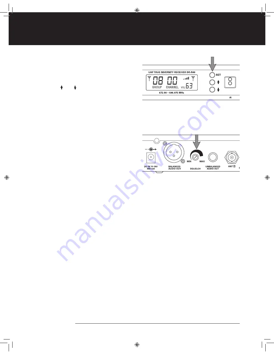
Adjusting the Audio Output
The Receiver Output Volume is displayed in the lower
right corner of the LCD display. Output level can be
adjusted by pressing the SET button 3 times to scroll
to the Volume setting. When the Volume indicator is
flashing, use the UP/ DOWN buttons to select a
volume setting between 0–63. The Volume indicator
will stop flashing after 10 seconds and the new value
is stored.
Adjusting the Squelch
SQUELCH adjusts the Receiver’s sensitivity to RF signals.
A high SQUELCH setting typically reduces the chance
of RF interference, but lowers the useable operating
distance. A low SQUELCH setting typically increases
operating distance, but increases the possibility of
unwanted interference.
The SQUELCH control on the DR-R40 receiver
simultaneously controls both the A and B True Diversity
receiver sections. The control should be adjusted
counterclockwise to the minimum RF squelch setting at
which the RF Level Meter and the Diversity Indicator will
remain lit while your transmitter is in normal use, up to
its anticipated maximum operating range. However, in
areas of high RF activity, the squelch control may need
to be adjusted clockwise.
If the transmitter is off and both the receiver signal and
diversity indicators are flickering or stay lit continuously,
the SQUELCH should be adjusted to a higher level
(clockwise for less mute sensitivity level). Be careful
not to select too high a clockwise setting, as this may
reduce the operating range below what is needed.
A range walk test will help in selecting the proper
level. If the range is not critical, note that a clockwise
(max SQUELCH) setting will also yield a quieter mute
function, which might be desired in certain applications.
Also note that the SQUELCH level is factory preset
at maximum sensitivity and operating range (i.e. turn
counterclockwise to MIN).
8868 Digital Ref 4600 Manual.indd 11
10/27/09 10:37:15 AM


