background image

----

----

----

----

----

----

----

----

----

----

----

----

----

----

----

----

----

----

----

----

----

----

----

----

----

----

----

----

----

----

----

----

----

----

----

----

----

----

----

----

----

----

----

----

----

----

----

----

----

----

----

----

----

----

----

----

Digital Projection 

MERCURY 5000gv


2. Installation 

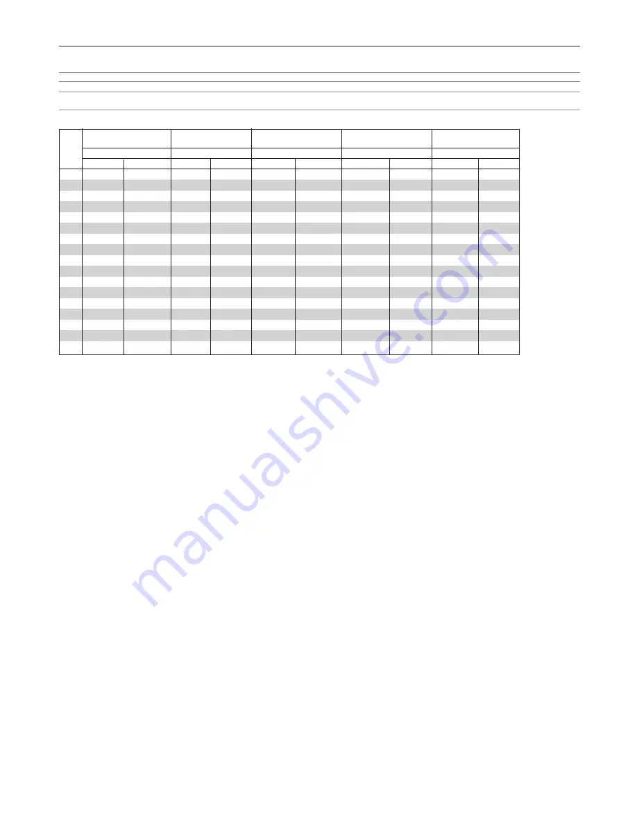
Table of Throw Distances and Screen Sizes for Optional Zoom Lenses 

NOTE: applicable to XGA and all wide-screen formats that use the full width of the DMD™. 

NOTE: Actual throw distances may vary from those shown in the table below by up to +/-5%.

More accurate figures are dependent on the lens extension data, yet to be confirmed (see formula below).

Screen 

size 

zoom 

(001-736) 

zoom 

(001-737) 

zoom 

(001-738) 

zoom 

(001-739) 

zoom 

(001-740) 

1.5 - 1.8 : 1 

1.8 - 2.25 : 1 

2.25 - 3.0 : 1 

3.0 - 4.5 : 1 

4.5 - 7.0 : 1 

(inches) 

(m) 

(inches) 

(m) 

(inches) 

(m) 

(inches) 

(m) 

(inches) 

(m) 

(inches) 

60 

-

1.8 

2.2 

-

72 

86 

-

2.2 

2.7 

-

86 

108 

-

2.7 

3.7 

-

108 

144 

-

3.7 

5.5 

-

144  216 

-

5.5 

8.5 

-

216  336 

67 

-

2.0 

2.5 

-

80 

96 

-

2.5 

3.1 

-

96 

121 

-

3.1 

4.1 

-

121 

161 

-

4.1 

6.1 

-

161  241 

-

6.1 

9.5 

-

241  375 

72 

-

2.2 

2.6 

-

86 

104 

-

2.6 

3.3 

-

104 

130 

-

3.3 

4.4 

-

130 

173 

-

4.4 

6.6 

-

173  259 

-

6.6 

10.2 

-

259  403 

80 

-

2.4 

2.9 

-

96 

115 

-

2.9 

3.7 

-

115 

144 

-

3.7 

4.9 

-

144 

192 

-

4.9 

7.3 

-

192  288 

-

7.3 

11.4 

-

288  448 

84 

-

2.6 

3.1 

-

101 

121 

-

3.1 

3.8 

-

121 

151 

-

3.8 

5.1 

-

151 

202 

-

5.1 

7.7 

-

202  302 

-

7.7 

11.9 

-

302  470 

90 

-

2.7 

3.3 

-

108 

130 

-

3.3 

4.1 

-

130 

162 

-

4.1 

5.5 

-

162 

216 

-

5.5 

8.2 

-

216  324 

-

8.2 

12.8 

-

324  504 

100 

-

3.0 

3.7 

-

120 

144 

-

3.7 

4.6 

-

144 

180 

-

4.6 

6.1 

-

180 

240 

-

6.1 

9.1 

-

240  360 

-

9.1 

14.2 

-

360  560 

120 

-

3.7 

4.4 

-

144 

173 

-

4.4 

5.5 

-

173 

216 

-

5.5 

7.3 

-

216 

288 

-

7.3 

11.0 

-

288  432 

-

11.0 

17.1 

-

432  672 

150 

-

4.6 

5.5 

-

180 

216 

-

5.5 

6.9 

-

216 

270 

-

6.9 

9.1 

-

270 

360 

-

9.1 

13.7 

-

360  540 

-

13.7 

21.3 

-

540  840 

180 

-

5.5 

6.6 

-

216 

259 

-

6.6 

8.2 

-

259 

324 

-

8.2 

11.0 

-

324 

432 

-

11.0 

16.5 

-

432  648 

-

16.5 

25.6 

-

648  1008 

200 

-

6.1 

7.3 

-

240 

288 

-

7.3 

9.1 

-

288 

360 

-

9.1 

12.2 

-

360 

480 

-

12.2 

18.3 

-

480  720 

-

18.3 

28.4 

-

720  1120 

210 

-

7.7 

9.6 

-

302 

378 

-

9.6 

12.8 

-

378 

504 

-

12.8 

19.2 

-

504  756 

-

19.2 

29.9 

-

756  1176 

240 

-

8.8 

11.0 

-

346 

432 

-

11.0 

14.6 

-

432 

576 

-

14.6 

21.9 

-

576  864 

-

21.9 

34.1 

-

864  1344 

250 

-

9.1 

11.4 

-

360 

450 

-

11.4 

15.2 

-

450 

600 

-

15.2 

22.9 

-

600  900 

-

270 

-

12.3  16.5 

-

486 

648 

-

16.5 

24.7 

-

648  972 

300 

-

13.7  18.3 

-

540 

720 

-

18.3 

27.4 

-

720  1080 

400 

-

18.3  24.4 

-

720 

960 

For screen sizes between 60" and 400" not indicated on the tables, use the formula below: 

Throw Distance (distance from front of casing to screen) = [Screen Width (W)  x  Throw Ratio (magnification)] +/- [ extension] 

(where [extension] = distance between front of casing and end of lens)

Example: Throw Distance for 2.5m wide screen using zoom lens 001-736 set to 1.6 : 1

Throw Distance


= 2.5m  x  1.6  = 4m +/- extension 
= 98” x 1.6 

= 157” +/- extension 

Lens extensions and useable ranges are as follows: 

magnification 

extension 

useable range 

to be 

Fixed lens 001-734 

0.8 : 1 

confirmed 

1.3m - 2.4m (4ft 3in - 8ft) 

Fixed lens 001-735 

1.2 : 1 

“ ” 

1.5m - 9.8m (4ft 10in - 32ft) 

Zoom lens 001-736 

1.5 : 1 
1.8 : 1 

“ ” 

1.8m - 6.1m (6ft - 20ft) 
2.2m - 7.3m (7ft 2in - 24ft) 

Zoom lens 001-737 

1.8 : 1 
2.25 : 1 

“ ” 

2.2m - 9.1m (7ft 2in - 30ft) 
2.7m - 11.4m (9ft - 37ft 6in) 

Zoom lens 001-738 

2.25 : 1 
3.0 : 1 

“ ” 

2.7m - 18.3m (9ft - 60ft) 
3.7m - 24.4m (12ft - 80ft) 

Zoom lens 001-739 

3.0 : 1 
4.5 : 1 

“ ” 

3.7m - 18.3m (12ft - 60ft) 
5.5m - 27.4m (18ft - 90ft) 

Zoom lens 001-740 

4.5 : 1 
7.0 : 1 

“ ” 

5.5m - 21.9m (18ft - 72ft) 
8.5m - 34.1m (28ft - 112ft) 

2-3 

Summary of Contents for MERCURY 5000gv

Page 1: ...MERCURY 5000gv DMD Projector User s Manual ...

Page 2: ...ii ...

Page 3: ...t EN 55022 1995 Limits and Methods of Measurement of Radio Disturbance Characteristics of Information Technology Equipment EN 60950 1992 Specification for Safety of Information Technology Equipment including Electrical Business equipment The technical documentation required to demonstrate that the products meet the requirements of the Low Voltage directive has been compiled by the signatory below ...

Page 4: ...ademarks of their respective holders RF Interference WARNING The Federal Communications Commission does not allow any modifications or changes to the unit EXCEPT those specified by Digital Projection in this manual Failure to comply with this government regulation could void your right to operate this equipment This equipment has been tested and found to comply with the limits for a Class A digita...

Page 5: ...nter damage caused by improper handling during transportation Do not eject a PC card or LAN card while its data is being accessed Doing so can damage your PC card or LAN card Lamp Replacement To replace the lamp follow all instructions provided on page 9 2 Be sure to replace the lamp when the message The Lamp has reached the end of its usable life Please replace the lamp appears If you continue to...

Page 6: ...Digital Projection MERCURY 5000gv vi ...

Page 7: ... line Help and Information 4 2 Using a USB Mouse 4 3 Using a USB HUB Function 4 3 Changing Background Logo 4 4 Making Freehand Drawings on Projected Image ChalkBoard 4 4 5 Using the Viewer 1 2 Making the Most out of the Viewer Function 5 2 Operating the Viewer Function from the Projector playback 5 3 8 Using the On Screen Menus 1 2 Basic Menu Operation 8 2 List of Direct Button Combinations 8 3 Me...

Page 8: ...Digital Projection MERCURY 5000gv viii ...

Page 9: ... Know Your Projector 1 4 2 3 Control Panel Features 1 6 Terminal Panel Features 1 7 4 Remote Control Features 1 9 Remote Control Precautions 1 11 Remote Control Battery Installation 1 11 Operating Range for Wireless Remote Control 1 11 Using the Remote Control in Wired Operation 1 12 ...

Page 10: ... E S T A B C 1 D E F 2 G H I 3 J K L 4 M N O 5 P Q R 6 S T U 7 V W X 8 0 Y Z 9 P O W E R I N P U T O F F I N F O P I X E L S O U N D O S D M A G N I F Y C T L F O C U S Z O O M M E N U A D D R E S S I M A G E P R O J E C T O R P O S I L E N S K E Y S T R E L I S T P I C T U R E A D J U S T W H I T E B A L B A M P G P I C T S H U T M U T E Remote control 102 161 and batteries AAx2 Remote cable 102 ...

Page 11: ...output or lamp life and provide for built in redundancy Smart security settings for password protection control panel lock menu lock and PC card protection key to help prevent unauthorized access and adjustments to the projector ADA508 and Executive Order 13221 Federal Government compliance 1 DigiView 10 bit video decoder for expanded black levels and adaptive gamma correction Digital photo viewer...

Page 12: ...ar cover Remote control sensor Remote control sensor Ventilation inlet 3 Getting to Know Your Projector Controls Terminal panel Left AC INPUT Connect the supplied power cable s three pin plug here Lens optional Terminal panel Right Remote control sensor Remote control sensor Ventilation outlet ...

Page 13: ...n MERCURY 5000gv 1 Introduction Feet rotate to fine adjust the height and level of the projector Ventilation outlet Remote control sensors 2 x 5 8 UNC mounting holes maximum depth 1 4 x M8 mounting holes maximum depth 16mm ...

Page 14: ...r 1 2 Lights while accessing a PC card 6 3D REFORM Button Press this button to enter 3D Reform mode to correct the keystone trapezoidal distortion and make the image square Press to toggle between Cornerstone and Keystone adjustment mode NOTE Pressing and holding this button for a minimum of 2 seconds will reset 3D Reform correction setting values to zero 3 2 1 7 AUTO ADJUST Button Use this button...

Page 15: ...he RGB2 input A commercially available audio cable is required 3 DVI IN Connector DVI D 24 Pin This connector can be used to accept digital signal output from a computer with a DVI connector DVI AUDIO Input Mini Jack Stereo Mini This is where you connect the audio output from your computer when connected to the DVI input A commercially available audio cable is required 4 RGB OUT Connector Mini D S...

Page 16: ...N the screen trigger output sends a low voltage trigger to the screen controller and the screen will go down When the projector is powered OFF the screen trigger stops sending a low voltage trigger to the screen controller and the screen will go up NOTE To use this feature you must turn on the Screen Trigger function See page 8 17 Stereo mini cable Tip 12V not supplied Ring 0V Sleeve ground 0V NOT...

Page 17: ...lect the menu of the item you wish to adjust When no menus appear these buttons work as a volume control Use these buttons to change the level of a selected menu item A press of the button executes the selection Pressing and holding CTL then pressing button works as a Back Space key in the entry screen Pressing and holding CTL then pressing this button moves the menu slider toolbar or dialog box 6...

Page 18: ...her or the power is turned off the main power 20 MUTE PICTURE Press to turn off the picture for a short period of time Press again to restore the picture 21 KEYSTONE R Press to display the Keystone Correction 3D Reform screen This button toggles between Cornerstone and Keystone When the test pattern is displayed while pressing and holding CTL pressing this button displays a red test pattern NOTE P...

Page 19: ...Batteries When it comes time to replace the batteries two AA type will be required 1 Press and open the cover 2 Align and insert the batteries according to the and indications inside the case 3 Replace the cover Operating Range for Wireless Remote Control The infrared signal operates by line of sight up to a distance of approximately 7m 20 feet and a 60 degree angle of the remote sensor The projec...

Page 20: ... of the supplied remote cable to the REMOTE 2 IN mini jack and the other end to the remote jack on the remote control NOTE Do not use this jack for anything other than intended use Connecting the wired remote control to the SC TRIGGER Mini Jack causes damage to the remote control Remote cable supplied REMOTE 2 IN ...

Page 21: ...Range 2 4 Optional Lens Installation 2 5 Making Connections 2 6 3 4 Connecting Your PC or Macintosh 2 6 To connect Scart Output 2 7 Connecting an External Monitor 2 7 Connecting Your DVD Player 2 8 Connecting Your VCR or Laser Disc Player 2 9 Connecting to a Network 2 10 Connecting the Supplied Power Cable 2 11 ...

Page 22: ...254 Screen width W inch Screen size x 4 5 Screen height H inch Screen size x 3 5 Table of Throw Distances and Screen Sizes for Optional Fixed Lenses Screen size Width W Height H inches m inches m inches 60 1 2 48 0 9 36 80 1 6 64 1 2 48 100 2 0 80 1 5 60 120 2 4 96 1 8 72 150 3 0 120 2 3 90 200 4 1 160 3 0 120 240 4 9 192 3 7 144 300 6 1 240 4 6 180 400 8 1 320 6 1 240 500 10 2 400 7 6 300 NOTE ap...

Page 23: ...13 7 360 540 13 7 21 3 540 840 180 5 5 6 6 216 259 6 6 8 2 259 324 8 2 11 0 324 432 11 0 16 5 432 648 16 5 25 6 648 1008 200 6 1 7 3 240 288 7 3 9 1 288 360 9 1 12 2 360 480 12 2 18 3 480 720 18 3 28 4 720 1120 210 7 7 9 6 302 378 9 6 12 8 378 504 12 8 19 2 504 756 19 2 29 9 756 1176 240 8 8 11 0 346 432 11 0 14 6 432 576 14 6 21 9 576 864 21 9 34 1 864 1344 250 9 1 11 4 360 450 11 4 15 2 450 600 ...

Page 24: ...directions cannot be obtained due to circular shape of lens example shift up and right see dotted box in diagram below NOTE example below shows only zoom lenses WARNING Installing the projector on the ceiling must be done by a qualified technician Tilting the projector from side to side by more than 12 from level will reduce lamp life see page iv Only use your projector on a solid level surface If...

Page 25: ...ce shock to the projector or the lens Do not touch the lens surface Doing so can degrade the optical performance Preparation Tools needed for installation A cross head screwdriver NOTE It is possble that the Lens Shift feature described on the previous page and in Section 3 Projecting an Image may have used to move the lens mount to the far right side making installation difficult If this is the c...

Page 26: ... D cable should be within 5 m 196 long The DVI DIGITAL connector accepts VGA 640x480 SVGA 800x600 1152x864 XGA 1024x768 and SXGA 1280x1024 up to 60Hz Audio cable not supplied IBM VGA or Compatibles Notebook type or Macintosh Notebook type IBM PC or Compatibles Desktop type or Macintosh Desktop type RGB signal cable not supplied To mini D Sub 15 pin connector on the projector NOTE For older Macinto...

Page 27: ...SCART adapter is obtainable from your Digital Projection dealer Contact your Digital Projection dealer for more information To RGB 2 IN Connecting an External Monitor You can connect a separate external monitor to your projector to simultaneously view on a monitor the RGB analog image you re projecting To do so 1 Turn off the power to your projector monitor and computer 2 Use a 15 pin cable to con...

Page 28: ... projector For a DVD player without a component video Y Cb Cr output use an Component video RCA x 3 cable not supplied S Video cable not supplied to connect an S Video output of the DVD player to the S Video input of the projector Use an appropriate type of audio cable not supplied to connect the desired type of audio from your DVD player to your audio equipment 3 Turn on the projector and DVD pla...

Page 29: ... your VCR or laser disc player connect the other end to the Video input on your projector an RCA to BNC adapter is necessary Use an audio cable not supplied to connect the audio from your VCR or laser disc player to your audio equipment if your VCR or laser disc player has this capability Be careful to keep your right and left channel connections correct for stereo sound 3 Turn on the projector an...

Page 30: ...CD ROM and the optional wireless LAN card SWL 2100 N you can control the projector wirelessly or send your PC screen image to the projector over the network using a computer Example of LAN connection Using the HTTP Server function 1 Configure your LAN settings such as IP address on the projector See LAN Mode on page 8 19 2 Start the Web browser on the computer connected to the network and execute ...

Page 31: ...on Connecting the Supplied Power Cable Connect the supplied power cable to the projector First connect the supplied power cable s three pin plug to the AC IN of the projector and then connect the other plug of the supplied power cable in the wall outlet ...

Page 32: ...2 Installation Digital Projection MERCURY 5000gv 2 12 ...

Page 33: ...3 2 2 Selecting a Source 3 3 3 Adjusting the Picture Size and Position 3 3 4 Correcting the Horizontal and Vertical Keystone Distortion DigiScale 3D Reform 3 4 5 Optimizing RGB Picture Automatically 3 6 6 Turning Up or Down Volume 3 6 7 Turning off the Projector 3 7 ...

Page 34: ... Use the SELECT or button to select one of the seven languages for the menu 2 Press the ENTER button to execute the selection 3 The Basic menu will be displayed in the language you have selected To close the menu press the CANCEL button After this has been done you can proceed to the advanced menu opera tion If you want you can select the menu language later See Language on page 8 13 NOTE To turn ...

Page 35: ...n by pressing the TEST button on the remote control or using the menu 4 Adjust the image position and the image size 1 Press and hold the CTL button and press the POSITION button to display the Lens Shift adjustment screen Use the SELECT button on the remote control or the LENS SHIFT button on the projector cabinet to move the image horizontally and vertically To close the Lens Shift adjustment sc...

Page 36: ... when the projector is cold Lens mechanism interacts differently when adjusting focus from one direction to the other For this reason final focus adjustments should be done in a specific direction For optimum focus follow the steps below For the zoom and the lens shift adjustment perform the normal procedures Preparation Recommended Warm up the projector for about 60 minutes Adjusting the Focus 1 ...

Page 37: ...hapes which can be corrected using the Corner stone adjustment When adjusting the Cornerstone beyond these limits you will get the mes sage Out of adjustment range and no correction can be done Should this happen do the Cornerstone adjustment again within the allowable range Due to limitations of accuracy within internal processes there may be some discrepancy of positions between the mouse cursor...

Page 38: ...n its adjustable range Menu items should be set as follows Aspect Ratio 1 33 1 4 3 Screen Type 1 33 1 4 3 Horizontal and Vertical are adjusted separately A combination of both adjustments limits 3D Reform in its adjustable range When Native is selected in Resolution 3D Reform is not available 5 Optimizing RGB Picture Automatically Adjusting the Image Using Auto Adjust Optimizing RGB image automati...

Page 39: ...r turning on the projector CAUTION Do not unplug the power cable from the wall outlet or do not turn off the main power under any one of the following circumstances Doing so can cause damage to the projector While the Hour Glass icon appears While the message Please wait a moment appears This message will be displayed after the projector is turned off While the cooling fans are running The cooling...

Page 40: ...3 Projecting an Image Digital Projection MERCURY 5000gv 3 8 ...

Page 41: ... and Sound 4 2 Enlarging and Moving a Picture 4 2 Getting the On line Help and Information 4 2 Using a USB Mouse 4 3 Using a USB HUB Function 4 3 Changing Background Logo 4 4 Making Freehand Drawings on a Projected Image ChalkBoard 4 4 2 3 4 5 6 7 ...

Page 42: ...n off the on screen display Press again to restore the on screen display PICT SHUT SOUND OSD move the magnified image use the SELECT button Return the image to the original size MUTE MAGNIFY ZOOM MUTE NOTE You can also turn off the on screen display forcibly by pressing and holding CTL and then pressing MUTE OSD Forced On Screen Mute Mode doing this again restores it In this case any adjustment wi...

Page 43: ...dle button wheel on a mouse With the middle button wheel you can use a scroll bar or click the middle button wheel to display or hide the Chalkboard toolbar 5 Using the USB HUB Function When using the projector with a PC via the supplied USB cable both the USB port type A on the projector can be connected to a USB supported scanner or other USB supported device USB Hub Function Example When connec...

Page 44: ... feature allows you to write and draw messages on a pro jected image NOTE The ChalkBoard feature is available only when a USB mouse is used From the menu select Tools ChalkBoard to display the ChalkBoard tool bar that contains the following icons NOTE You can also display the ChalkBoard tool bar by clicking the scroll button on your USB mouse Pen Eraser Drive Exit Color Capture Clear Hide Pen Left...

Page 45: ...5 Using the Viewer 1 Making the Most out of the Viewer Function 5 2 2 Operating the Viewer Function from the Projector playback 5 3 ...

Page 46: ...XP 2000 Slides can be created by capturing the currently displayed image Control screen for displaying lists of slides and editing Microsoft Windows and PowerPoint are registered trademarks of Microsoft Corporation Removing the PC Card Press the eject button slowly The eject button card pops out a little Press the eject button slowly again Grasp the edges of the PC card and pull it out Push and in...

Page 47: ...tions of the menu This al lows you to move on to the next slide when Manual Play is selected Stop This allows you to stop Auto Play while you are play ing back and to resume playing from the selected slide or folder when Auto Play is selected Jump Displays a list of slides while you are playing back Select Displays a list of folders while you are playing back Drive Switches between PC Card slot Se...

Page 48: ...from the menu you will get a tool bar You can capture an image directly using the tool bar when the menu is not displayed NOTE Unless a PC card is inserted into the PC Card slot of the projector the Capture feature is not available The Card Error display means that the free space of the PC card is insufficient for saving images Make more space available on the card by erasing unwanted images with ...

Page 49: ...ws you to display a list of all the files stored in the PC card so that you can select a file you want to display You can also sort files by file name or date or display the file Although a list of all the files in the PC card is displayed you can view files in idx text HTML JPEG and BMP format only Selecting BMP and JPEG files automatically switches to the Viewer source See also page 5 3 NOTE Thi...

Page 50: ...5 Using the Viewer Digital Projection MERCURY 5000gv 5 6 ...

Page 51: ...Using the Projector in a Network 1 Introduction 6 2 Supported Equipment 6 3 Equipment Connections and Settings 6 4 Software Installation 6 5 Starting Exiting the Software 6 6 Troubleshooting 6 7 2 3 4 5 6 ...

Page 52: ...ith Microsoft PowerPoint 95 97 2000 2002 to an independent index format with a simple operation to enable direct playback with the viewer function of the projector When using Microsoft PowerPoint 2000 2002 Viewer PPT Converter 2 0 can be started from PowerPoint by means of add in registration to PowerPoint Image Express Utility 1 0 Using a network environment 2 this program enables the screen imag...

Page 53: ...ns are run at the same time Network Environment A LAN that supports TCP IP or a wireless LAN environment is a requirement when used For information on supported LAN cards contact Digital Projection For wireless LAN connection use Digital Projection optional wireless LAN card 001 723 or 001 762 for France Supported OS Windows 98 Windows 98 Second Edition Windows Me Windows 2000 Professional Windows...

Page 54: ...arious items NOTE When switching the power of the projector on off with the projector control function please set Projector Options Setup Page 4 Idle Mode to On Settings at the Personal Computer Side Perform the regular LAN connections settings according to the instruction manual of the LAN card adapter There are no special settings to be made in the connections with the projector When Making Conn...

Page 55: ...he Welcome screen not appear 1 Click Start 2 Click Run The Run screen will appear 3 Enter the CD ROM drive name e g Q and then SETUP EXE to Open O 4 Click OK The Welcome screen will appear 2 Click Next at the Welcome screen The End User License Agreement screen will appear Please carefully read the contents of the End User License Agreement 3 If you agree click Yes If you do not agree please click...

Page 56: ...e started from the supplied CD ROM 1 From the Start menu click Program Projector User Supportware Viewer PPT Converter 2 0 Dynamic Image Utility 2 0 will start Reference A function equivalent to Viewer PPT Converter 2 0 can also be executed from the Dynamic Image Utility 2 0 Tools Converting PowerPoint file menu Viewer PPT Converter 2 0 can also be started from the Microsoft PowerPoint 2000 2002 T...

Page 57: ...talled Problem Viewer PPT Converter 2 0 does not function PPTC 2 0 Countermeasures computer PPT Converter 2 0 on a personal computer on which PowerPoint has been installed Check Points Has Microsoft PowerPoint been installed on the personal Install PowerPoint on the personal computer Or install Viewer Problem When using the projector control function the projector power does not switch on DIU 2 0 ...

Page 58: ...t Office assistant 4 IME 5 Moving pictures Problem Operation of this projector software becomes unstable DIU 2 0 IEU 1 0 Check Points Countermeasures When the network settings of the projector or personal Please restart the projector and the personal computer When computer are changed while this projector software i e changes are to be made to the network settings exit the Dynamic Image Utility 2 ...

Page 59: ...nager Network Adapter and then click Properties R and set the device usage to Not used Problem Sometimes it takes a long time for screen transmission from the personal computer to the projector IEU 1 0 Check Points Countermeasures Transmission time may be long depending on the image pattern When screens are sent to multiple projectors simultaneously a larger number of projectors will result in lon...

Page 60: ...6 Using the Projector in a Network Digital Projection MERCURY 5000gv 6 10 ...

Page 61: ... and Connecting the Projectors 7 2 2 Adjusting and Registering Signals to Be Projected 7 5 3 Adjusting the Lens Shift Zoom and Focus to Clearly Display all projected patterns 7 5 4 Link Mode Setting 7 5 5 List of Menu Items Available in Link Mode 7 6 ...

Page 62: ...s plus the weight of the lens Assigning Projector IDs You can operate multiple projectors with the same remote control To do so 1 Select Projector Options Link Mode Settings Projector ID and assign an ID number to each projector See also page 8 18 2 Select the same communication speed for both the projector NOTE Do not turn on Master or Slave at this time 3 On the remote control specify the ID num...

Page 63: ...ojectors and the screen is in the middle part of the recommended range for both lenses NOTE The optional lenses for this projector have different geometrical distortions in wide zoom and tele Select the best zoom position for stacking where the geometrical distortion is as small as possible Stacking the Projectors Place the projectors at the proper height for best screen to projector relationship ...

Page 64: ...rminal of the master projector to the PC CONTROL IN terminal of the slave projector until all the projectors are connected 3 Turn all the projectors on and roughly make some optical adjustments to each projector Bi directional RS232C cable not supplied S Video cables not supplied Distribution amplifer Example Composite signal S Video cable not supplied Video equipment NOTE Connect a commercially a...

Page 65: ...rojctor then Red of the slave projector 2 Adjust the Lens Shift by pressing and holding CTL and pressing the POSITION button on the remote control For lens shift adjustable range see page 2 4 and 2 5 Lens Shift Adjustable Range 3 Zoom the lens in and out by pressing and holding CTL and pressing the MAGNIFY ZOOM button on the remote control 4 Adjust the lens focus by pressing and holding CTL and pr...

Page 66: ...r 2 Remote Control 2 ZOOM Projector 2 Remote Control 2 MENU SELECT ENTER CANCEL Projector Remote Control POWER Projector 3 POWERON Remote Control 3 POWEROFF Remote Control 3 INPUT Remote Control 1 MUTE PICTURE Remote Control MUTE SOUND Remote Control MUTE OSD Remote Control 1 Unregistered signal is displayed on the master projector only and the picture is muted on the slave projector 2 Adjustment ...

Page 67: ...tions 8 7 Capture Source Select 8 7 Entry List 8 7 Adjust Source 8 7 Picture 8 8 8 28 8 28 Video Adjust 8 8 Projector Information Picture Management 8 9 Image Options 8 10 Test Pattern Option Adjust 8 10 Signal Type 8 11 Sound 8 11 Ref Adjust 8 12 3D Reform 8 12 Screen 8 12 Reference White Balance 8 12 Reference Color Correction 8 12 Factory Default 8 13 Menu 8 13 Link Mode 8 18 Password 8 23 Tool...

Page 68: ...e control or the projector cabinet you can enable all the items within that submenu Also you can turn on an item within the submenu without placing a check mark on the main menu item NOTE Up to 12 main menu items within Custom Menu Edit not including submenu items can be selected 3 In order for the changes to take effect use the SELECT or button on the remote control or the projector cabinet to hi...

Page 69: ...n remote control Displays the magnifying glass icon CTL BS Deletes one letter or numeral in the entry screen CTL MUTE OSD Turns off the on screen display forciblly CTL MENU ADDRESS Displays the remote ID entry window CTL IMAGE PROJECTOR Sequentially selects the Projector Options sub menu CTL POSITION LENS Displays the Lens Shift adjustment window CTL KEYSTONE R Turns on red Available only when the...

Page 70: ...8 4 8 Using the On Screen Menus Digital Projection MERCURY 5000gv 3 Menu tree NOTE The item appears dimmed on the menu it is unavailable ...

Page 71: ...8 5 Digital Projection MERCURY 5000gv 8 Using the On Screen Menus NOTE The shaded item indicates the default setting ...

Page 72: ...8 6 8 Using the On Screen Menus Digital Projection MERCURY 5000gv When selecting PC Card the Network Type and the WEP setting screens appear ...

Page 73: ... on your remote control or the projector cabinet to highlight the menu for the item you want to project RGB1 2 Viewer DVI DIGITAL LAN Video RGB 1 Video S Video RGB 1 S Video Entry List Displays the list of the entry signals Use the SELECT buttons on your remote control or the projector cabinet to select the signal and press the ENTER button on the remote control or the projector cabinet to display...

Page 74: ...egistered signals in the Entry List The following buttons are not available for the currently projecting signals 1 The Cut and Paste buttons on the Entry Edit Command screen 2 The Input Terminal button on the Entry Edit screen Adjust Source Picture Brightness Adjusts the brightness level or the back raster intensity Contrast Adjusts the intensity of the image according to the incoming signal Satur...

Page 75: ...ks that appear more like shades of gray to provide a true black and white image at high contrast NOTE This feature is not available for 480p 576p and HDTV signals Contrast Enhancement This option allows you to provide a high contrast image in a bright scene 3D Y C Separation This option turns on or off the 3 dimension separation feature NOTE This feature is available for NTSC3 58 of Video signal o...

Page 76: ...ck phase or to reduce video noise dot interference or cross talk This is evident when part of your image appears to be shimmering Use the and buttons to adjust the image Use Phase only after the Clock is complete Position Adjusts the image location horizontally and vertically using the SELECT and buttons Aspect Ratio You can select the aspect ratio for input signal Select the appropriate aspect ra...

Page 77: ... are made in such circumstances Use the SELECT or button to adjust the VD level VD Delay Adjustment This feature is used to correct vertical jitter of a signal NOTE When connecting with a scan converter If an image from the scan converter is not correctly displayed adjust to select the best level point so that the image is displayed correctly Field Invert This feature is used to correct diagonal l...

Page 78: ...nactive Position This feature adjusts the vertical position of the image when viewing video with an aspect ratio selected When some aspect ratios are selected in Image Options the image is displayed with black borders on the top and bottom You can adjust the vertical position between top and bottom NOTE This option is available only when 1 78 1 16 9 1 85 1 and 2 35 1 are selected in Screen Type an...

Page 79: ...urrent signal to the factory preset levels All the items in Adjust Source and Sound can be reset NOTE Locked signals in Entry List cannot be reset Projector Options Menu Menu Page 1 Selecting Menu Language Language You can choose one of seven languages for on screen instructions The options are English German French Italian Spanish Swedish and Japanese Selecting Menu Mode Menu Mode This feature al...

Page 80: ...xample to display February press 0 and 2 2 Type in time Time is expressed in the 24 hour format For example 6 00 p m is entered as 18 00 3 Select OK and press ENTER Closing the window allows the clock to start The current year month date and time are displayed on the top of the screen NOTE The projector has a built in clock The clock will keep working for about 3 days after the main power is turne...

Page 81: ...uperimposed TEXT 1 4 Text is displayed in full screen OFF This exits the closed caption mode Sync Termination RGB1 This function is used to select the impedance of the sync signal Select 75Ω or Hi Z NOTE This should be 75Ω for normal use Select the Hi Z when inputting a TTL signal Setup Page 2 Setting Viewer Options Show Folder List If this option is checked when the Viewer source is selected on t...

Page 82: ... and S Video separately and VIDEO or S VIDEO for RGB1 connector Setup Page 4 Enabling Auto Adjust Auto Adjust When Auto Adjust is set to On the projector automatically determines the best resolution for the current RGB input signal to project an image using Digital Projection s DigiScale Intelligent Pixel Blending Technology The image can be automatically adjusted for position and stability Horizo...

Page 83: ...ini cable Setup Page 5 Remote Sensor This option determines which remote sensors on the projector are enabled in wireless mode The options are front rear right or left All checked boxes indicate that they can accept the infrared signal from the supplied remote control S Video Mode Select This feature is used to select the S Video signal detection mode This allows identifying of the S Video signals...

Page 84: ...amps Lamp 1 on the right side and Lamp 2 on the left side when viewed from the front Interval This allows you to specify the time for switching between the two lamps alternately This option is available only when Lamp1 or Lamp2 is selected When Auto is selected and one lamp has reached the end of its usable life the other lamp is turned on The lamp cannot be turned off for 60 seconds immediately a...

Page 85: ... more information on inserting or ejecting a LAN card see page 5 2 Either PC Card Slots 1 or 2 can accept LAN card If two LAN cards are inserted into both PC card slots the first inserted one is effective The standard built in LAN feature and a commercially LAN card are available for network connection but only one can be used at a time mutual exclusion CAUTION Make sure that the LAN card is remov...

Page 86: ...DNS server on the network connected to the projector 12 numeric characters are used Domain Name Type in domain name of the network connected to the projector Up to 60 alphanumeric characters can be used Mode Select communication method when using wireless LAN Infrastructure Select this option when communicating with one or more equipment connected to the wireless or wired LAN network via an access...

Page 87: ...ton to change to ASCII to set the key in ASCII digit You can toggle this button between ASCII and HEX The key can also be set in hexadecimal digit Hexadecimal uses 0 to 9 and A to F Up to 10 characters can be set in 64 bit and up to 26 characters in 128 bit NOTE Only numbers can be entered when you use the remote control Source Input buttons Depending on your network environment acquiring an IP ad...

Page 88: ...e This option notifies your computer of an error message via e mail when using wireless or wired LAN The error message will be notified when the projector lamp has reached the end of its usable life or an error occurs in the projector Sample of a message sent from the projector The lamp is at the end of its usable life Please replace the lamp Projector Name X X X X Lamp 1 Hour Meter xxxx H Lamp 2 ...

Page 89: ...hlighted and then press the ENTER button 2 Type the same password again Highlight OK on the Enter the Password screen and press the ENTER button Your password will be assigned Delete To delete your password 1 Highlight Delete and press the ENTER button The Current Password screen will be displayed 2 Use the Software keyboard to type your password Highlight OK on the Current Password screen and the...

Page 90: ...se the SELECT button to select Register and press the ENTER button Downloaded data will be registered and be displayed in the list window 5 Use the SELECT button to select Keyword and use the software keyboard to enter a keyword NOTE To use a PC card as a protect key you must also set up a keyword Please make a note of your keyword This completes registration of your PC card To enable Security use...

Page 91: ...d on by entering the Release Code your Security will be disabled NOTE Some types of PC cards cannot be registered as your protect key It is recommended that you register two or more PC cards in case you lose or damage your registered PC card Formatting your registered PC card will disable your protect key function Tools Provides tools for setting On Off timer sleep timer capturing images displayin...

Page 92: ...ill enter the standby or idle mode Enabling the On or Off Timer 1 To execute the setting select Active 2 Select OK and press the ENTER button NOTE When one program or more are specified all the settings are active NOTE The settings will be executed in numerical order Finished settings will be automatically deleted NOTE The On Off Timer will not work while the cooling fans are running or an error m...

Page 93: ...Files feature allows you to display a list of all the files stored in the PC card so that you can select a file you want to display You can also sort files by file name or date or display the file See page 4 4 Changing Background Logo You can change the default background logo using the PC Card Files feature See page 4 4 NOTE File size must be 256KB or less Other file formats than JPEG and BMP are...

Page 94: ... A warning message will appear on screen near the expected end of life This will also be shown by the Lamp Indicators on the control panel at the rear of the projector see page 1 6 NOTE The life of a Standard lamp part number 001 742 life is typically 1500 hours in Normal mode The lamp life however may be decreased under certain conditions and the lamp could reach end of life within the specified ...

Page 95: ...9 Routine Maintenance 1 Replacing the Lamp 9 2 2 Replacing or Cleaning the Filter 9 3 3 Cleaning the Cabinet and the Lens 9 3 ...

Page 96: ...o make sure that no dust or dirt can get into the cabinet during lamp replacement Clean the outside of the cabinet before opening the rear cover To replace the lamp module 1 Loosen the rear cover fastening by turning it through 45 and open the cover using the support if the projector is upside down NOTE There is an interlock on the rear cover to prevent the risk of electrical shock Do not attempt ...

Page 97: ...erlock on the rear cover to prevent the risk of electrical shock Do not attempt to circumvent this interlock 2 Remove the single cross headed screw securing the top edge of the filter and remove the filter 3 Cleaning the Cabinet and the Lens 1 Turn off the projector before cleaning 2 Clean the cabinet periodically with a damp cloth If heavily soiled use a mild detergent Never use strong detergents...

Page 98: ...9 Routine Maintenance Digital Projection MERCURY 5000gv 9 4 ...

Page 99: ...net Dimensions 10 7 Pin Assignments of D Sub RGB Input Connector 10 7 Compatible Input Signal List 10 8 REMOTE 1 Connector 10 9 PC Control Codes and Cable Connection 10 10 2 3 4 5 6 7 8 Cable Connection 10 10 PC Control Connector D SUB 9P 10 10 9 Using Software Keyboard 10 10 0 1 Operation Using an HTTP Browser 10 11 ...

Page 100: ...emorydeviceandaUSBmemorycardreader whenconnectingaUSBmousetotheprojector UsingaUSBHUBthatallowsmultipleUSBmemorydevicesorcard readersisnotsupportedeither DonotdothefollowingwhiletheUSBmemorydeviceorUSBmemory card reader s access indicator is lit or flashing while data is being accessed DoingsocandamageyourUSBmemorydeviceorUSB memorycardinthereader Backupyourdataincaseitwillneedtobe restored Pullin...

Page 101: ...Power unit will not work correctly 0 5 sec OFF 4 cycle 0 5 sec ON Fanerror Cooling fan has stopped Contact 0 5 sec OFF your dealer Steady light Red Circuit error A circuit has failed Contack your dealer Orange Control key locked You have pressed control panel key when Control Key Lock is enabled Green Idle condition Lamp 1 2 Indicator Indicator Condition Projector Condition Note Off Light off Blin...

Page 102: ...ture is blurred Adjust the focus See page 3 4 Reposition the projector to improve its angle to the screen See page 3 3 Ensure that the distance between the projector and screen is within the adjustment range of the lens See page 2 2 Condensation may form on the lens if the projector is cold brought into a warm place and is then turned on Should this happen let the projector stand until there is no...

Page 103: ... fixed 80 150 diagonal 1 2 1 fixed 60 400 1 5 1 8 1 zoom 60 200 1 8 2 25 1 zoom 60 250 2 25 3 0 1 zoom 60 400 3 0 4 5 1 zoom 60 300 4 5 7 0 zoom 60 240 0 8 1 fixed 1 3m 2 4m 4ft 3in 8ft 1 2 1 fixed 1 5m 9 8m 4ft 10in 32ft 1 5 1 8 1 zoom 1 8m 7 3m 6ft 24ft 1 8 2 25 1 zoom 2 2m 11 4m 7ft 2in 37ft 6in 2 25 3 0 1 zoom 2 7m 24 4m 9ft 80ft 3 0 4 5 1 zoom 3 7m 27 4m 12ft 90ft 4 5 7 0 zoom 5 5m 34 1m 28ft...

Page 104: ...0 60 Hz Input Current Power Consumption 10 0 A 100 VAC 4 0A 240 VAC 1000W Dual Lamp mode 750W Single Lamp mode 1W Standby Mechanical Dimensions 531 mm W x 270 mm H x 535 mm D 20 9 W x 10 7 H x 21 1 D not including protrusions Net Weight 25kg 55 lbs not including lens Environment Operational Temperatures 32 95 F 0 to 35 C 20 80 humidity Storage Temperatures 14 122 F 10 to 50 C 20 80 humidity Regula...

Page 105: ...Signal 1 Red Cr 2 Green or Sync on Green Y 3 Blue Cb 4 Ground 5 Ground 6 Red Ground Cr Ground 7 Green Ground Y Ground 8 Blue Ground Cb Ground 9 No Connection 10 Sync Signal Ground 11 SCART Sync Sync 12 Bi directional DATA SDA 13 Horizontal Sync or Composite Sync 14 Vertical Sync 15 Data Clock Video signal 0 7Vp p Analog Sync signal TTL level RGB 2 Input only All dimensions in mm and inches ...

Page 106: ...UN 1152 x 900 61 796 65 95 SGI 1152 x 900 71 736 76 05 VESA 1280 x 960 60 60 VESA 1280 x 1024 63 981 60 02 MAC 1280 x 1024 69 89 65 2 HP 1280 x 1024 78 125 72 01 SUN 1280 x 1024 81 13 76 11 VESA 1280 x 1024 79 976 75 03 VESA 1280 x 1024 91 146 85 02 SXGA 1400 x 1050 HDTV 1080p 1920 x 1080 67 5 60 SDTV 576i 625i 15 6 50 SDTV 576p 625p 31 5 50 HDTV 1080i 1125i 1920 x 1080 33 75 60 Interlace HDTV 108...

Page 107: ...O S VIDEO Slot 1 1 RGB 2 Slot 1 2 RGB1 S VIDEO DVI DIGITAL VIEWER RGB1 VIDEO Slot 2 1 Slot 2 2 LAN When combinations other than specified in the above table are selected or when no optional board is inserted in the Slot 1 and 2 the input will be switched to RGB 1 by default The term SHORT means to connect with pin 15 When in the external control mode the POWER Source Input PICTURE MUTE and SOUND M...

Page 108: ...0H 00H 13H SOUND MUTE ON 02H 12H 00H 00H 00H 14H SOUND MUTE OFF 02H 13H 00H 00H 00H 15H ON SCREEN MUTE ON 02H 14H 00H 00H 00H 16H ON SCREEN MUTE OFF 02H 15H 00H 00H 00H 17H NOTE Contact your local dealer for a full list of PC Control Codes if needed Cable Connection Communication Protocol Baud rate 38400 bps Data length 8 bits Parity No parity Stop bit One bit X on off None Communications procedur...

Page 109: ...ddress for Operation via a Browser Regarding the actual address that is entered for the address or entered to the URL column when operation of the projector is via a browser the host name can be used as it is when the host name corresponding to the IP address of the projector has been registered to the domain name server by a network administra tor or the host name corresponding to the IP address ...

Page 110: ...s to input 1 of the Slot 2 Slot 2 2 Switches to input 2 of the Slot 2 RGB1 VIDEO Switches to Video of the RGB1 connector RGB1 S VIDEO Switches to S Video of the RGB1 connector Projector Status This displays the condition of the projector Remaining Lamp 1 2 Time Displays the remaining life of the lamp 1 2 as a percentage Lamp 1 2 Hour Meter Displays how many hours the lamp 1 2 has been used Project...

Reviews: