background image

Digital Projection 

E-Vision Laser 7500 & 8500 Series

Rev D January 2017

Page 20

Important Information

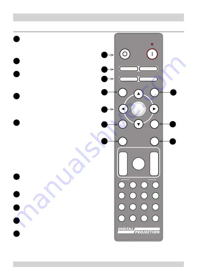
Remote Control Reference

1


Power ON/OFF

Turns the projector on and off.

To turn the projector off, press the OFF 

button twice within five seconds.

2


Pic Mute OPEN / CLOSE

Shows and hides the projected image.

3


OSD ON / OFF

Enables and disables screen timeout 

messages and showing the OSD 

during projection.

4

 MENU

Access the projector OSD (on-screen 

display). If the OSD is open, press 

this button to go back to the previous 

menu.

5


Navigation (arrows and OK)

Navigate through the menus with the 

arrows, confirm your choice with 

OK

.

In lens adjustment modes, the arrows 

are used to move, zoom or focus the 

lens. See 

11

 below.

In lens adjustment modes, or when 

the OSD is not showing, the 

OK


button switches between modes: 

Shift Adjustment

 and 

Zoom / 

Focus Adjustment

.

6

 EXIT

Close the current OSD page and return 

to the level above.

7

 FREEZE

Freeze the current frame.

8

 DEFAULT

Restore default settings.

9

 INFO

Access information about the projector.

10

 RE-SYNC

Re-synchronise with the current input 

signal.

Pic Mute

MENU

EXIT

INFO

HDMI1

OK

OFF

ON

ALT

LENS

FOCUS

ZOOM

IN

OUT

IN

OUT

SHIFT

2

1

3

HDMI2

DVI

DISPLAYPORT HD-T

3GSDI

VGA

COMP1 COMP2

BRI

TEST

CON

GAMMA

R

G

B

ALL

3D

EYE

PIP

SWAP

4

5

6

7

8

9

0

ALT

ADDR

OSD

OFF

ON

DEFAULT

FREEZE

RE-SYNC

A

B

C

D

USER PRESET

OPEN

CLOSE

1

2

5

6

8

4

9

7

3

10

Summary of Contents for E-Vision Laser 7500 Series

Page 1: ...Rev D January 2017 117 440D E Vision Laser 7500 Series E Vision Laser 8500 Series Super High Brightness Digital Video Projector 3 Important Information...

Page 2: ...420 1360 powerinfo digitalprojection com www digitalprojection com Digital Projection China 101 A 2006 100029 Rm A2006 ShaoYaoJu 101 North Lane Shi Ao International Center Chaoyang District Beijing 1...

Page 3: ...ture 8 Interlock switches 8 General precautions 9 Installation precautions 10 Operation and configuration precautions 11 Compliance with international standards 11 RF Interference 11 Noise 11 European...

Page 4: ...ons are closely followed ELECTRICAL WARNING this symbol indicates that there is a danger of electrical shock unless the instructions are closely followed WARNING this symbol indicates that there is a...

Page 5: ...Laser Product is designated as Class 3R during all procedures of operation LASER LIGHT AVOID DIRECT EYE EXPOSURE Do not point laser or allow laser light to be directed or reflected toward other people...

Page 6: ...YEUX APPAREIL LASER DE CLASSE 3R longueur d onde 450 460nm maximum nergie de impulsion 0 376 mJ dur e de impulsion 0 74 ms GB 7247 1 2012 IEC EN 60825 1 2007 CAUTION Possibly hazardous optical radiati...

Page 7: ...may cause undesired operation CAN ICES 3 A NMB 3 A Caution Do not open the cover No user serviceable parts inside Avertissement ne pas ouvrir le couvercle Le produit ne contient aucune pi ce interne...

Page 8: ...The laser aperture is located as indicated below 1 Laser aperture Interlock switches Three interlock switches installed at the main frame inside the cover will power off the system individually when a...

Page 9: ...expose the projector to rain or moisture and do not place any liquids on top of the projector Unplug before cleaning and use a damp not wet cloth Do not touch the power plug with wet hands Do not touc...

Page 10: ...ry area away from sources of dust moisture steam smoke sunlight or heat The projector is heavy Use safe handling techniques when lifting the projector Do not drop or knock the projector Before install...

Page 11: ...pment has been tested and found to comply with the limits for a Class A digital device pursuant with Part 15 of the FCC Rules These limits are designed to provide reasonable protection against harmful...

Page 12: ...nt the projector ensuring that it is at a suitable distance from the screen for the image to fill the screen Set the adjustable feet so that the projector is level and perpendicular to the screen The...

Page 13: ...ocket 2 Voltage selection The VOLTAGE SELECT switch must be set to match the power supply you are using Voltage of power supply used Position of VOLTAGE SELECT switch 100 130VAC outlet 200 240VAC sing...

Page 14: ...ss OFF on the remote control or POWER on the control panel then press again to confirm your choice The POWER indicator on the control panel will start flashing amber the system will go out and the coo...

Page 15: ...Lens menu The Lens menu provides access to the Lens Control setting and the Lens Center command Lens Control allows Zoom Focus and Shift adjustment using the arrow buttons The setting operates in Zoom...

Page 16: ...ng the lens avoid using excessive force as this may damage the equipment The lens is shipped separately Take care to preserve the original lens packaging and protective caps for future use The project...

Page 17: ...ff and fully disconnected from its power supply When changing the lens avoid using excessive force as this may damage the equipment The lens is shipped separately Take care to preserve the original le...

Page 18: ...Digital Projection E Vision Laser 7500 8500 Series Rev D January 2017 Page 18 Important Information Control Panel Reference POWER INPUT AUTO SYNC ASPECT CENTER LENS PIC MUTE 1 2 3 4 5 6 7 8 9 10 11 12...

Page 19: ...uttons Each of these buttons moves the lens in the specified direction 11 FOCUS plus and minus buttons Used to move the focus in and out 12 ZOOM plus and minus buttons Used to zoom in and out Projecto...

Page 20: ...rows confirm your choice with OK In lens adjustment modes the arrows are used to move zoom or focus the lens See 11 below In lens adjustment modes or when the OSD is not showing the OK button switches...

Page 21: ...MI 2 CON numeric input 2 Select the HDMI 1 input Use with ALT to bring up the Contrast control then adjust the value with the LEFT and RIGHT arrow buttons 16 HDMI 1 BRI numeric input 1 Select the HDMI...

Page 22: ...put 9 Select the Component 2 input 23 ADDR ALL Assign and unassign an IR remote address To assign an address 1 Press and hold this button until the indicator starts flashing 2 Release this button and...

Reviews: