background image

4-28

DL3800 DS1 Inverse Multiplexer User Guide—February 1999

4

RAM Software Options 

RAM Software Options - Query RAM Software

This feature determines when a valid software image exists in RAM by 
checking the CRC and image ID. The query indicates if the software can be 
activated in the unit. This is important if a remote software download is 
being done from a DL3900 to a DL3800 or the other way around. 

The following response messages are possible:

RAM Image is valid.

 - CRC is valid, Image ID is valid

RAM Image is active - no reboot necessary.

 - CRC is valid, Image 

ID is valid, but images are identical.

RAM Image is invalid (Product ID Error) xxxxxx

 - CRC is valid, 

Image ID is xxxxxx.

RAM Image is invalid (Size too small)

 - Header indicated the code 

buffer is too small.

RAM Image is invalid (Size too big)

 - Header indicated the code 

buffer is beyond its range.

RAM Image is invalid (CRC error)

 - CRC is invalid.

An image ID is a string consisting of DL3800, DL3900, DL3800E, or 
DL3800/DL3900. The image ID DL3800/DL3900 is reserved for use in a 
future application.

This command does not activate the software if it is downloaded and is 
pending activation, nor does it indicate the software revision of the 
downloaded image.

Querying the Remote Unit is performed by Þrst logging into the remote 
unit from the Main Menu, then navigating to this menu.

RAM Software Options - Activate RAM Software

This feature activates downloaded software by copying the code from 
RAM to FLASH and then rebooting the unit. If a valid (that is, Image ID 
and CRC are valid) software image does not exist in RAM, the command 
fails and a reboot will not occur.

An extended loss of power causes the non-activated software download to 
be lost.

Modifying this setting in the Remote Unit is performed by Þrst logging 
into the remote unit from the Main Menu, then navigating to this menu.

Summary of Contents for DL3800 DS1

Page 1: ...DL3800 DS1 Inverse Multiplexer User Guide Part 098 10380 01 Rev J February 1999...

Page 2: ...ormal and proper use will be free from defects in material and workmanship for a period of 24 months from the date of shipment to buyer THE FOREGOING WARRANTY IS EXCLUSIVE AND IN LIEU OF ALL OTHER WAR...

Page 3: ...h respect to the contents of this document and speci cally disclaims any implied warranties of merchantability or tness for any particular purpose Further Digital Link Corporation reserves the right t...

Page 4: ...the telephone company may discontinue your service temporarily If possible they will notify you in advance But if advance notice is not practical you will be noti ed as soon as possible You will be in...

Page 5: ...telephone jack If the trouble does not persist and appears to be with this unit disconnect the unit from the telephone line and discontinue use of the unit until it is repaired Please note that the te...

Page 6: ...vi DL3800 DS1 Inverse Multiplexer User Guide February 1999...

Page 7: ...Record xxi Chapter 1 Quick Install Guide 1 1 Purpose 1 1 Configuration 1 1 Equipment Needed 1 1 Setup 1 2 Terminal Log on 1 2 Terminal Configuration 1 2 Unit Configuration 1 2 DTE Configuration 1 2 Ne...

Page 8: ...er Connection 3 3 T1 Network Connection 3 4 DTE Cable And Connection 3 4 ASCII Terminal and SNMP Connection 3 5 Direct Connection 3 5 Modem Connection 3 5 Telnet Connection 3 5 Daisy Chaining 3 6 Chap...

Page 9: ...Login Configuration 4 30 SNMP Configuration 4 33 In Band SNMP to Remote 4 36 Save Configuration 4 36 Tests 4 36 DTE Network Loopback 4 37 Payload Loopback 4 38 Line Loopback 4 38 Local Loopback 4 38...

Page 10: ...4 Line Loopback 5 15 Local Loopback 5 15 Configuration Menu 5 15 Node Configuration 5 17 DTE Configuration Menu 5 22 Network Config 5 22 NET N Config 5 23 Network Thresholds 5 24 Chapter 6 Diagnostics...

Page 11: ...l A 3 Diagnostics A 3 Power A 3 Environmental A 4 Physical Connectors A 4 Appendix B Pinouts B 1 Terminal Connection B 1 DTE Connectors B 1 T1 Network Pin Assignments B 4 DB 25 to DE 9 Adapter Pinouts...

Page 12: ...Table of Contents xii...

Page 13: ...1 INVERSE MULTIPLEXER MAIN MENU 4 3 Figure 4 2 Main Menu with remote unit selected 4 5 Figure 4 3 ALARMS AND STATUS MENU 4 6 Figure 4 4 STATISTICS MENU 4 8 Figure 4 5 STATISTICS MENU Screen 1 4 9 Fig...

Page 14: ...5 Figure 4 14 SOFTWARE DOWNLOAD MENU 4 25 Figure 4 15 LOGIN CONFIGURATION MENU 4 31 Figure 4 16 SNMP CONFIGURATION MENU 4 33 Figure 4 17 TESTS MENU 4 37 Figure 4 18 Loopbacks Within the DL3800 4 38 Fi...

Page 15: ...16 Table 4 7 NETWORK CONFIGURATION MENU Options 4 19 Table 4 8 Login Configuration Options 4 32 Table 4 9 SNMP Configuration Options 4 33 Table 5 1 Front Panel LEDs 5 3 Table 5 2 NET Statistics Menu...

Page 16: ...25 to RS 449 DTE Connector Pin Assignments B 3 Table B 5 Network Pin Assignments B 4 Table B 6 DB 25 to DE 9 Pinouts B 4 Table B 7 External Clock Pinouts B 5 Table B 8 DTE Clock Rates B 6 Table C 1 U...

Page 17: ...discussion of features and bene ts and a sample application Chapter 3 Installation provides guidelines for placing and securing the DL3800 in the operation site Use this chapter to nd out about comma...

Page 18: ...to one of four levels of severity NOTE Follow guidelines in this or the previous paragraph to use the Digital Link product more effectively CAUTION Follow guidelines in this or the previous paragraph...

Page 19: ...ne placeholder that you replace with a real name or value To delete a le type rm lename Book titles new words or terms or words that need to be emphasized Refer to Chapter 6 in the User Guide These ar...

Page 20: ...edure if you need to return a unit for service or repair 1 Contact the Digital Link Customer Service Department at 408 745 4200 orviae mailatera dl com orfaxarequestto 408 745 4240 to obtain an ERA Eq...

Page 21: ...manual All suggestions and comments are appreciated DOCUMENT CHANGE RECORD Digital Link Technical Publications FAX 408 745 6250 Email techpubs dl com Date Issue Rev Description Pages Affected July 199...

Page 22: ...xxii DL3800 DS1 Inverse Multiplexer User Guide February 1999...

Page 23: ...the rest of this user s guide The con guration items discussed in this chapter will be based on the CSU version of the DL3800 but can be easily adapted to con gure DSX units as well Recommended con gu...

Page 24: ...and password press Return twice and the Main Menu on the DL3800 should appear The default unit number is 0 Terminal Configuration Only change the con guration items listed below Leave other options at...

Page 25: ...ally will be ESF B8ZS Primary clock Xmt Network assuming carrier or remote unit providing timing Primary clock RCV should be set to AUTO Con gure SER to Immediate Confirm and select EXIT Select Exit a...

Page 26: ...1 4 DL3800 DS1 Inverse Multiplexer User Guide February 1999 1...

Page 27: ...ent to the DTE application as the multiple T1 circuits act as a single high speed data link The DL3800 can accept up to a 31 milliseconds differential delay between individual T1 circuits thus providi...

Page 28: ...d the DL3800 can automatically restore the T1 and data rate The user can con gure control and monitor the DL3800 through the front panel an ASCII terminal locally or remotely via a modem or remotely i...

Page 29: ...erse multiplexing communications This frame is constructed by using one payload bit in each frame for 16 consecutive frames For T1 the inverse multiplexing frame is the rst bit after the framing bit F...

Page 30: ...in the ALARMS and STATUS MENU No event is registered for this status item in the Event History An IMUX T1 circuit is re established as soon as the mismatched circuits are disconnected and re connecte...

Page 31: ...on as well as supporting unit con guration test and maintenance activities Finally the Controller block supports the front panel display terminal port and SNMP port interfaces The front panel consists...

Page 32: ...loopback capabilities for ease of maintenance Numerous alarm conditions are reported including user selectable alarm thresholds for T1 line parameters The DL3800 also provides alarm relay contacts for...

Page 33: ...ithout having to move up to more expensive T3 transport retaining the investment made in T1 technology and equipment A typical application is shown in Figure 2 3 Figure 2 3 Typical Application for DL3...

Page 34: ...2 8 DL3800 DS1 Inverse Multiplexer User Guide February 1999 2...

Page 35: ...ropriate data and network interface cables and connectors if ordered Power cord 3 Mount the DL3800 See Mounting The DL3800 on page 3 2 4 Connect Power Cables and Connections See Power Cables And Conne...

Page 36: ...ion on page 4 16 ASCII terminal MOUNTING THE DL3800 Rack Mounting The DL3800 is shipped with mounting ears attached to the unit ready for rack mounting onto a 19 inch rack A 19 inch rack mounting kit...

Page 37: ...C power cord to the DL3800 and plug into the nearest AC outlet DC Power Connection The Digital Link DL3800 DS1 Inverse Multiplexer can also be powered by a 48 to 72 VDC power source The DC power conne...

Page 38: ...socket connector for V 35 or RS 449 compatible DTEs If using a HSSI interface the cable connecting the DL3800 to the DTE consists of 25 twisted pairs with an overall foil braid shield The DL3800 end...

Page 39: ...settings of the modem must match the terminal or workstation port default settings baud rate 9600 eight bits no parity and two stop bits If these parameters are not the same recon gure the Unit defaul...

Page 40: ...52 01 or twelve units part 154 00053 01 To place an order contact the Digital Link Sales department at 408 745 6200 If using a cable other than the above see Terminal Connection on page B 1 for Termin...

Page 41: ...nd log off a particular unit follow these procedures 1 Type ve Ctrl X commands in a row followed by Enter or Return to return a roll call of all Node Numbers on the chain This feature is useful when t...

Page 42: ...ess Enter Type any other key and the change will not be made This will cause the terminal to continue to prompt the user to con rm the change s To abort the change move the highlight bar to Exit and p...

Page 43: ...er This is crucial in inter node communications The Node name Penguin is user de ned The user can use this eld to uniquely describe the node within the network The date and time are give in mm dd yy a...

Page 44: ...ress and Name in the header should change to the new unit as shown in Figure 4 2 Table 4 1 Main Menu Menu Description Select Local Remote Allows the user to move between the Main Menu of the Local and...

Page 45: ...ARMS AND STATUS items being reported by the DL3800 To access this screen move the highlight bar in the INVERSE MULTIPLEXER MAIN MENU to Alarms And Status and press Enter The ALARMS AND STATUS display...

Page 46: ...Table 4 2 Alarms and Status Network Common Equipment DTE Not present External Alarm HSSI Channel Lpbk LOS Proc Restart User Lpbk LOF RAM Test Fail User Loopback AIS det ROM Checksum Fail V 35 LT Lpbk...

Page 47: ...et Sync CA On Reset Code Detected LC On CRC Threshold SES Threshold UAS Threshold BPV MN MJ OOF MN MJ BPV 15 Min MN MJ CRCs 15 Min MN MJ ES 15 Min MN MJ SES 15 Min MN MJ UAS 15 Min MN MJ BPVs 24 Hr MN...

Page 48: ...or Red Alarms or Major Alarm Thresholds being exceeded the Alarm Status display will read ACTIVE If the T1 Network Con guration is set to NEVER USE and a good T1 is connected the Alarm Status display...

Page 49: ...er to clear the display and reset the counters If the counters were reset within the past 24 hours CUMULATIVE 2 will not display any errors Figure 4 5 STATISTICS MENU Screen 1 To view additional pages...

Page 50: ...re no LOS and no AIS events ES A In ESF format only this is the count of one second intervals with exactly one CRC 6 no SEF and no LOS events ES B In ESF format only this is a count of one second inte...

Page 51: ...ing window approximately 10 3 will create a Major Alarm and 5 OOFs in a 600 second sliding window approximately 10 6 will create a Minor Alarm BPV Bipolar Violations This display provides the number o...

Page 52: ...IGURATION MENU item provides access to a series of Sub Menus to con gure various parameters of the unit DTE and network Highlight Configuration in the INVERSE MULTIPLEXER MAIN MENU and press the Enter...

Page 53: ...nfiguration Highlighting Unit and pressing the Enter key accesses the UNIT CONFIGURATION MENU shown in Figure 4 9 The con gurable items and options are described in Table 4 5 The following parameters...

Page 54: ...l the desired choice appears Automatic Backup This feature allows the user to back up the database to the EEProm automatically at certain intervals or manually To change the present backup mode highli...

Page 55: ...00 19 200 and 38 400 Default 9600 Terminal Parity Bits This feature selects the terminal parity To set or change the local terminal parity move the highlight bar to Terminal Parity Bits and press the...

Page 56: ...Figure 4 10 is an example of the DTE CONFIGURATION MENU and Table 4 6 describes the menu items Figure 4 10 DTE CONFIGURATION MENU Table 4 6 DTE CONFIGURATION MENU Options Parameter Description Action...

Page 57: ...mode the 3800 places the signal high when you have a clear signal from the network indicating the T1 is up and running Default Automatic DSR Data Set Ready This allows the user to Assert DeAssert or...

Page 58: ...ows the user to Assert DeAssert or set to Automatic the TM leads To change or set the TM lead status use the up and down arrow keys to highlight TM and use the Space Bar to toggle between Assert DeAss...

Page 59: ...toggle between Report and Mask Highlight Confirm and press the Enter key to confirm any change Default Mask Active Restore Mode This option selects the Active Restore Mode for each of the T1 network p...

Page 60: ...desired choice appears Default B8ZS Equalization DSX 1 Only This allows the user to select Line Equalization distance for the individual T1 network ports To change the present Equalization level use t...

Page 61: ...the present EGL use the up and down arrow keys to highlight the EGL item in the appropriate line for the desired port and use the Space Bar to toggle between 36 dB and 26 dB until the desired choice a...

Page 62: ...twork ports To change the present Secondary Clock Source use the up and down arrow keys to highlight either Xmt or Rcv on the Secondary Clock Source line and use the Space Bar to toggle between the ch...

Page 63: ...reshold is exceeded To Enable or Disable the FALLBACK feature highlight the appropriate item and use the space bar to select your choice Second Error Restoral Interval This item selects the time that...

Page 64: ...hlight the appropriate item and press Enter When the highlight bar is blank type in the number desired Save Configuration This option allows the user to manually back up the database to EEPROM at any...

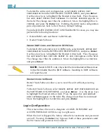
Page 65: ...Enter The SOFTWARE DOWNLOAD MENU Figure 4 14 will appear on the screen Figure 4 14 SOFTWARE DOWNLOAD MENU To download new software to the DL3800 the following equipment is needed A PC with a disk driv...

Page 66: ...typing a Ctrl L will refresh the screen If it is set up for multidrop mode see Log In Log Off on page 4 1 on how to Log in to a unit 4 Select the Software Download option from the SYSTEM UTILITIES MEN...

Page 67: ...RAM to Flash and reboots A system restart power cycle that occurs after the download but before the activation will not activate the new software Loss of power causes the non activated software downl...

Page 68: ...code buffer is beyond its range RAM Image is invalid CRC error CRC is invalid An image ID is a string consisting of DL3800 DL3900 DL3800E or DL3800 DL3900 The image ID DL3800 DL3900 is reserved for us...

Page 69: ...Software Activation is enabled on the target unit the software is downloaded to the RAM of the target unit and is activated by copying the code from RAM to FLASH memory and then rebooting The performa...

Page 70: ...highlight the Desired Action eld Press the space bar until DELETE RAM CODE AND REVERT TO ROM CODE appears in the eld The change must then be con rmed Move the highlight bar to CONFIRM and press Enter...

Page 71: ...aracters in length To enter a name or password move the highlight bar to the appropriate line and column and type in the alphanumeric designation Move the highlight bar to CONFIRM and press Enter to c...

Page 72: ...Allows the user access to view only screens The user is not allowed to make any changes or initiate tests No Access Not allowed to access the menu screens Terminal Automatic Logout Allows the user to...

Page 73: ...e the highlight bar to SNMP CONFIGURATION in the CONFIGURATION MENU and press Enter Figure 4 16 is an example of the SNMP CONFIGURATION MENU and Table 4 9 describes the SNMP parameters Figure 4 16 SNM...

Page 74: ...cross the T1s Read Community String This alphanumeric identifier up to 32 characters in length identifies a portion of the SNMP network that is able to read messages from the node To set or change the...

Page 75: ...this is not strictly necessary SNMP Baud Rate This feature selects the SNMP port s baud rate To set or change the SNMP port baud rate move the highlight bar to SNMP Baud Rate and press the Space Bar...

Page 76: ...s of the remote unit the packet is discarded The unit responds to SNMP packets with its IP address from an NMS with any IP address no change from the current functionality The unit transmits SNMP resp...

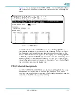
Page 77: ...he display When that selection appears in the display move the highlight bar to CONFIRM and press the Enter key To cancel a test that is running move the highlight bar to DTE NETWORK LOOPBACK Use the...

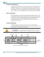
Page 78: ...ne loopback loops the data received from the T1 network back towards the network The data is regenerated prior to being looped back however no additional processing of the data is done by the DL3800 T...

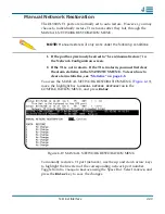
Page 79: ...istics in the STATISTICS MENU To learn how to clear alarm statistics see Statistics on page 4 8 To access the MANUAL NETWORK RESTORATION MENU Figure 4 19 move the highlight bar to MANUAL NETWORK RESTO...

Page 80: ...uide February 1999 4 Logout This allows the user to manually logoff the unit instead of waiting for the provisioned automatic logoff time for the unit to logoff automatically Highlighting LOGOUT and p...

Page 81: ...eatures six LEDs for the DTE port one for each of the T1 networks three for the DL3800 status and one for Network Test DISPLAY OVERVIEW The DL3800 has a 16 character uorescent front panel display The...

Page 82: ...cel operations or exit to a higher level menu loop from a sub menu loop This button doubles as a left arrow button in a few situations Up Arrow and Down Arrow Buttons The up arrow button is used to mo...

Page 83: ...oved CTS Clear To Send indicator to DTE Yellow CTS to DTE is active Off CTS has been removed indicating that the DL3800 is not sending valid data DTR Data Terminal Ready Indicator Yellow DTR from DTE...

Page 84: ...to Off in the Unit Con guration menu Refer to Unit Con guration on page 4 13 When a user needs to take a unit out of Protected Mode but a terminal is not available the following procedure can be used...

Page 85: ...resumes at the completion of Self Test When the Self Test message is removed the default message DL3800 Inverse Multiplexer appears on the display TOP MENU The Top Menu loop consists of ve items 1 DL...

Page 86: ...Menu is used for displaying Node Status DTE Status and Status of each installed T1 network The 24 hour line data is only available with the terminal interface or through the Network Manager The data i...

Page 87: ...by the remote unit will be displayed SELECT REMOTE SELECT LOCAL Pressing the Down Arrow cursor button when the default message is in the display brings the message SELECT REMOTE or R SELECT LOCAL to...

Page 88: ...y installed from two to eight will have status lines in this menu RETURN TO MAIN MENU DISPLAY ITEM NODE STATUS DTE STATUS NET 1 STATUS ENTER EXIT EXIT EXIT EXIT Use Arrow keys to view statistics EXIT...

Page 89: ...ET 1 STATUS through NET 8 STATUS if all are installed Use the up and down arrows to select the T1 Network to be monitored and press the ENTER button Use the up and down arrow to view further status it...

Page 90: ...the current interval Z the number of valid 15 minute intervals since the error counters were reset 0 through 96 CUR X X the current interval TOTL X X the number of errors in the current interval Tabl...

Page 91: ...the onset of the condition leading to a failure CSS The Controlled Slip Second is a count of one second intervals containing one or more controlled slips OOF This is the number of seconds that the sig...

Page 92: ...sing ENTER when the appropriate menu appears in the display DTE TESTS NET 2 TESTS NET 3 TESTS NET 4 TESTS ENTER EXIT ENTER EXIT LINE LOOPBACK TEST MENU EXIT EXIT EXIT EXIT EXIT Return to Menu item TES...

Page 93: ...e a DTE NET LOOP from the DL3800 front panel press ENTER when DTE NET LOOP appears in the display When a DTE DTE LOOP is in operation a plus sign will appear after DTE NET LOOP in the display DTE Net...

Page 94: ...rough this Menu a PAYLOAD PAYLD LOOPBACK a LINE LOOPBACK and a LOCAL LOOPBACK To access NETWORK TESTS MENU from the TEST MENU press ENTER when NETWORK TESTS MENU for a particular T1 circuit NET 1 thro...

Page 95: ...al Loopback The local loopback is used to verify the operation of the DTE and connections The local loopback loops the data received from the DTE back towards the DTE at the network interface To initi...

Page 96: ...time and communications port It also shows the user the hardware and software versions NODE C ONFIG NETWORK CONFIG NET 1 CONFIG NET 2 CONFIG E N TE R E XIT E N TE R E XIT DTE Use U p and Down A rrows...

Page 97: ...r can be changed After each letter or number is selected press ENTER to Backup Database Used to manually back up the database to EEPROM DTE CONFIG MENU Used to set the line mode for the DTE DATA port...

Page 98: ...nd be available for change To abort any change press EXIT before you press ENTER ENTER UNIT NUMBER DATE TIME NODE COMM PORT ENTER ENTER EXIT ENTER EXIT ENTER EXIT Unit number menu Date and Time menu N...

Page 99: ...as in entering the Unit ID Date Time The Date Time are set at the factory PST They appear in the display as June 07 1998 09 44 49 To change the Date Time follow the procedure described under Node Conf...

Page 100: ...ices are Use or Ignore XON XOFF Terminal Multidrop If the local terminal is connected to more than one DL3800 it must be in Multidrop Mode If it is connected to only one unit this feature can be disab...

Page 101: ...TE 9600 ENTER PARITY EVEN Arrow keys change baud rate EXIT ENTER EXIT ENTER ENTER EXIT ENTER EXIT EXIT Arrow keys change stop bits STOP BITS 2 EXIT STOP BITS 2 Arrow keys change length of data bits EX...

Page 102: ...of the Con gurable items are described in detail in Network Thresholds on page 5 24 of this User Manual Network Config The NETWORK CONFIG MENU allows the user to change various con gurable items commo...

Page 103: ...18 of this User Manual ENTER EXIT NETWORK CONFIGURATION Menu ENTER EXIT EXIT EXIT ENTER EXIT Return to Config Menu item Network Configuration ENTER EXIT EXIT EXIT ENTER EXIT PRI TX CLK INT EXIT Up and...

Page 104: ...X CONFIGURATION Menu NET ESF NET ESF Up and Down arrow buttons change framing to D4 and ESF ENTER EXIT NET AMI Up and Down arrow buttons change line code between AMI and B8ZS EXIT EXIT ENTER EXIT Retu...

Page 105: ...will start the menu and allow the user to scroll using the down or up arrow buttons through the following options Table 5 6 NET THRESHOLD Options and Values OPTION VALUE CON CRCS 010 CON CRCS OFF CON...

Page 106: ...hange an alarm threshold value use the Up and Down arrow buttons to get to that particular alarm and press ENTER Use the Up or Down buttons to raise or lower the value 24 HR MI CRCS 10 24 HR MJ CRCS 1...

Page 107: ...ND NETWORK TESTS MENU to initiate and terminate one DTE test and three network tests The four tests are DTE NETWORK Loopback Payload Loopback LINE Loopback LOCAL Loopback To initiate a loopback test i...

Page 108: ...e received data port signal back to the data port and the received T1 processor signal back to the T1 network It can test a problem whose source is the T1 line LOCAL Loopback Test Use the LOCAL Loopba...

Page 109: ...rce may be the Telco T1 line wiring between the Telco demarcation points the DL3800 at one or both ends or the cable between the T1 line reporting errors and the DL3800 The TEST LED on the DL3800 turn...

Page 110: ...doesn t power up If the DL3800 is AC powered make sure it is plugged into a live AC outlet If it is DC powered make sure the respective DC leads are not crossed Check all fuses for opens replace as n...

Page 111: ...ed T1 port to verify that the T1 port is functioning on the unit The NETWORK T1 LEDs are constantly yellow Make sure no tests are being initiated on the affected T1ports Individual T1 port tests cause...

Page 112: ...sure that the correct T1 cable is connected to the correct T1 port You must restore the T1 line manually if it is configured for use w Manual Restore in Network Configuration and a threshold or alarm...

Page 113: ...Make sure the DTE device can run to a DCE in loopback If configured for SCTE the DTE device must be able to recognize an inverted clock If it does not set the clocking to SCT Make sure the DTE device...

Page 114: ...minal emulation program Make sure you are using a straight through cable with pin 8 CTS cut at the terminal end Make sure the Comm Port parameters match the terminal s and the DL3800 has a unique ID I...

Page 115: ...raming Formats D4 or ESF ESF FDL Protocols AT T 54016 ANSI T1 403 Line Code AMI or B8ZS Transmit Line Rate 1 544 Mbps 50 ppm Receive Line Rate 1 544 Mbps 135 ppm Synchronization Internal Loop timed or...

Page 116: ...or V 35 RS 449 Rate Up to 12 224 Mbps Connector Types DB 25 Socket V 35 RS449 50 pin Socket Amplimite HSSI Number of Ports One Item Interface Interface Devices Terminal or Modem Protocol User friendl...

Page 117: ...CTS DTR network data test T1 1 through T1 8 status MAJ alarm MIN alarm Item Interface Loopbacks DTE Network Payload Line Local Self Test Checks Unit Circuitry and Memory on power up Alarms Relay dry c...

Page 118: ...rating Temperature 0o C to 50o C Storage Temperature 20o C to 60o C Relative Humidity 0 to 95 Non Condensing Altitude 200 ft to 13 500 ft 60 1 m to 4 1 m above sea level Item Dimensions Mounting 19 in...

Page 119: ...t between units but not to the Terminal 5 SG Signal Ground Bidirectional Table B 2 HSSI DTE Connector Pin Assignments SIGNAL DIRECTION PIN SIDE PIN SIDE SG Signal Ground 1 26 RT Receive Timing To DTE...

Page 120: ...E From DTE 14 18 39 43 SG Signal Ground 5 ancillary from DCE 19 44 5 ancillary from DCE To DTE 20 24 33 49 SG Signal Ground 25 50 Table B 3 DB 25 to V 35 DTE Connector Pin Assignments TWISTED PAIR V 3...

Page 121: ...le B 4 DB 25 to RS 449 DTE Connector Pin Assignments TWISTED PAIR RS449 DB25 BLU RED 17 35 BLU BLK 7 25 4 19 YEL BLK 24 6 16 3 BRN BLK 22 4 14 2 BLK GRN 11 18 6 25 YEL RED 27 8 13 5 ORN RED 13 31 8 10...

Page 122: ...l Link DE 9 ribbon cable to be compatible with a DB 25 connector on the terminal port BLK BLU 19 NC 7 NC DRAIN 1 NC Table B 5 Network Pin Assignments PIN SIGNAL 1 Send towards Network Tip T1 9 Send to...

Page 123: ...External Clock connector are as follows Per RS 422 requirements the receiver has an input sensitivity of 200 mV over the input voltage range of 7 V The frequency is 1 544 MHz 50 ppm and the impedance...

Page 124: ...ser Guide February 1999 B DTE Clock Rates Table B 8 DTE Clock Rates NETWORKS DTE CLOCK RATE MBPS B8ZS 1 1 528 2 3 056 3 4 584 4 6 112 5 7 640 6 9 168 7 10 696 8 12 224 AMI 1 1 336 2 2 672 3 4 008 4 5...

Page 125: ...e FRONT PANEL On UNIT NUMBER 0 TERMINAL BAUD RATE 9600 TERMINAL PARITY BITS 8 bits No parity TERMINAL STOP BITS 2 XON XOFF Enabled MULTIDROP Enabled Table C 2 DTE Settings DTE Setting DTE INTERFACE V...

Page 126: ...SOURCE Xmt Int Rcv Net 2 DSU MODE Inverse Mux Standard Operation SUPPRESS YELLOW DET Disabled Table C 4 Network Threshold Settings Network Threshold Setting CONSECUTIVE THRESHOLDS Fallback Disabled Se...

Page 127: ...MMUNITY STRING Public TRAP COMMUNITY STRING Public SNMP BAUD RATE 9600 BITS PARITY 8 bits No parity STOP BITS 2 Table C 6 Test Settings Tests Setting ALL LOOPBACKS TESTS Off Table C 5 SNMP Configurati...

Page 128: ...C 4 DL3800 DS1 Inverse Multiplexer User Guide February 1999 C...

Page 129: ...which the signal carrying the binary value alternates between positive and negative polarities ANSI American National Standards Institute Coordinates the development of U S voluntary national standar...

Page 130: ...by the receiver Bit Error Rate BER The percentage of received bits that are in error relative to a speci c amount of bits received usually expressed as a number referenced to a power of 10 bps Bits pe...

Page 131: ...enerated signal providing a timing reference for a transmission link used to control timing functions such as sampling interval signaling rate and duration of signal elements code conversion The proce...

Page 132: ...to Send A signal issued by the DSU to indicate it is connected to the digital network and is ready to accept data CV Code Violation Any code violation D D4 Framing format for T1 transmission that plac...

Page 133: ...l 3 The 44 736Mbit s digital signal carried on a T3 facility DSU CSU Data Service Unit Channel Service Units The pair of communications devices that connect an in house line to an external digital cir...

Page 134: ...al which indicates that the DTE is ready for operation DTR Data Terminal Ready Signal from DTE to DSU CSU E EER Excessive Error Rate Determined by counting the number of T1 T3 code violations during a...

Page 135: ...t reports clear error counters and activate loop backs FG Frame Ground A signal from DTE to DSU CSU fractional bandwidth DTE loopback A loopback test that loops back the signal at the network interfac...

Page 136: ...trol protocol any related control of data links by speci ed series of bits rather than by control characters I IP address A unique 32 bit identi er for a TCP IP host on a network IP addresses are norm...

Page 137: ...nt It is used to describe network management variables multiplexer Any device that allows two or more users to share a common physical transmission medium Employed in pairs where each device performs...

Page 138: ...ignal unchanged for a zero where a change in voltage state signals a one bit and the absence of a change denotes a zero bit value O OOS Out of Service A digital network trouble signal OOF Out of Frame...

Page 139: ...art 68 Rules such as public switched digital service PSDS switched 56 19 2 Kbps service 64 Kbps service and synchronous digital data with secondary channel RLSD Receive Line Signal Detect a data port...

Page 140: ...rom the main channel It does not carry data messages and is used for diagnostic or supervisory purposes serial transmission A sequential transmission of bits constituting an entity of data over a data...

Page 141: ...nd receiving devices are synchronized T T1 A digital carrier facility used to transmit a DS 1 formatted digital signal at 1 544 Mbps T 1 normally can handle 24 voice conversations each one digitized a...

Page 142: ...nts are received ESF framing only V V 35 A CCITT standard for the trunk interface between a network access device and a packet network It de nes signaling for data rates greater than 19 2 Kbps V 52 Te...

Reviews: