System Module,
Continued
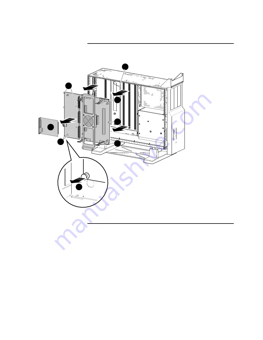
Figure 7–25 Removing the System Module
LJ-02932-TI0
5
3
4
Continued on next page
7–53
Page 1: ...gital service personnel who perform maintenance work on the DEC 3000 Model 500X AXP workstation The guide is also intended for Digital customers who have a self maintenance agreement with Digital This...
Page 2: ...on of the software described in this documentation is authorized only pursuant to a valid written license from Digital or the third party owner of the software copyright No responsibility is assumed f...
Page 3: ...pter Overview 3 1 4 Diagnostic Testing Chapter Overview 4 1 5 SCSI Utilities Chapter Overview 5 1 6 Troubleshooting Chapter Overview 6 1 Power or Fan Failures 6 2 7 Removing and Replacing FRUs Chapter...
Page 4: ...d Spares List D 1 Index Figures 1 1 Front View 1 6 1 2 Rear View 1 8 2 1 System Module Jumper Locations 2 2 2 2 Internal Cabling 2 4 2 3 Power Cabling 2 5 6 1 Regulator Module Connections 6 6 6 2 Powe...
Page 5: ...t Fan 7 42 7 21 Removing a Memory Motherboard 7 45 7 22 Memory Module Removal and Replacement 7 48 7 23 System Module Power Connections 7 51 7 24 TURBOchannel Connections 7 52 7 25 Removing the System...
Page 6: ......
Page 7: ...ervice Information guide Four chapters and one appendix provide new information on the Model 500X system Chapter 1 provides an overview of the DEC 3000 Model 500X AXP CPU memory subsystem and network...
Page 8: ...ge to equipment and software Warning Provides information to prevent personal injury Key Keys and switches that are labeled appear in a box For example Return indicates that you press the Return key o...
Page 9: ...tion The following documents provide additional information about the DEC 3000 Model 500X AXP workstation Document Order Number DEC 3000 Model 500X AXP Owner s Guide EK D5AXP OG DEC 3000 Model 500X AX...
Page 10: ......
Page 11: ...ule Memory subsystem Power supply Regulator module The DEC 3000 Model 500X AXP system provides support for Up to four SCSI internal disk drives Two 5 25 inch half height removable SCSI devices Up to s...
Page 12: ...des the following components TOY NVR controller chip Two serial line controllers ISDN interface with audio I O Two SCSI controllers Ethernet controller 256K byte of flash ROM Two TURBOchannel option s...
Page 13: ...rk LAN by using an attachment unit interface AUI or thickwire or 10BaseT twisted pair cable The selection thickwire or twisted pair is software controllable SCSI Interface The SCSI interface consists...
Page 14: ...system module To have an operational memory subsystem all four MMBs must be present The memory arrays are spread among the four MMBs Each bank of memory consists of eight memory modules two on each M...
Page 15: ...ect mapped caches Icache instruction cache Dcache data cache The system employs a second level cache to help minimize the performance penalty of misses and write throughs to the primary cache This sec...
Page 16: ...ure 1 1 shows the controls lights and devices on the front of the DEC 3000 Model 500X AXP system Table 1 1 describes their function Figure 1 1 Front View Line In 1 2 3 4 5 LJ 02490 TI0 6 7 8 9 10 11 C...
Page 17: ...tages are present on the power supply On Off switch Turn the system unit on and off 0 Fan failure indicator light Check whether a fan has failed Halt button Put the system in console mode Diagnostic d...
Page 18: ...ocation of switches connectors and modules on the rear of the DEC 3000 Model 500X AXP system Table 1 2 describes their function Figure 1 2 Rear View ISDN Hz S3 1 3 4 5 6 8 10 11 LJ 02982 TI0 2 1 0 3 4...
Page 19: ...odem External SCSI port Connect small computer system interface SCSI peripheral devices Printer alternate console switch Select the function of the printer alternate console port Five TURBOchannel slo...
Page 20: ......
Page 21: ...l 500 500S Guide For information on the following topics see the configuration chapter in DEC 3000 Model 500 500S AXP Service Information General configuration rules System module jumper locations Mod...
Page 22: ...Locations Figure 2 1 shows the location of jumpers the serial ROM and the sense cable connection on the system module Table 2 1 describes the jumpers Figure 2 1 System Module Jumper Locations 1 2 3 4...
Page 23: ...e Description Comments Default Setting Serial ROM Sense cable connection Must be installed Installed Serial ROM jumpers Jumper location 0 only 200 MHz jumper Must be installed Enabled Test pins Used b...
Page 24: ...ws cable connections between modules and disks in the DEC 3000 Model 500X AXP system Figure 2 2 Internal Cabling LJ 02936 TI0 Removable Media Fixed Disk Fixed Disk I O Module LSM Module Audio Module F...
Page 25: ...re 2 3 shows power connections between the power supply disks fans the system module and the regulator module Figure 2 3 Power Cabling LJ 02935 TI0 Fan Removable Media Fixed Disk Fan Fan Power Supply...
Page 26: ......
Page 27: ...information on using the console see Chapter 3 in DEC 3000 Model 500 500S AXP Service Information That chapter covers the following topics Console Command List Commands BOOT CONTINUE DEPOSIT EXAMINE H...
Page 28: ......
Page 29: ...testing see Chapter 4 in DEC 3000 Model 500 500S Service Information That chapter covers the following topics FRU Code Table List of Diagnostics Running Diagnostic Tests Entering and Exiting Console a...
Page 30: ......
Page 31: ...S Manual For information on utilities see Chapter 5 in DEC 3000 Model 500 500S Service Information That chapter covers the following topics SCSI Utility List Show Device Utility Hard Disk Eraser Utili...
Page 32: ......
Page 33: ...ers the following topics System Device FRU Codes Power Up LED Error Codes 84 Fail Code Troubleshooting Tables System Problems Monitor Problems Mouse Tablet Problems Keyboard Problems Drive Problems Ne...
Page 34: ...e LED is off NOTE Record the condition of LEDs before the unit is powered down If the unit has been powered down you must wait 60 seconds before the unit can be powered up again Fan Failure LED On If...
Page 35: ...form the following steps If you replace a part power up the unit if the problem persists go on to the next step unless instructed otherwise See Figures 6 1 and 6 2 for cable connection locations Befor...
Page 36: ...J2 and J3 on the regulator module 6 1 5 Power up the unit If the DC OK LED is off replace the regulator module If the DC OK LED is on power down the unit and reseat the connection between the system...
Page 37: ...11 11 Power up the unit Connect the 5 1 V B cable to the power supply 6 2 12 Power up the unit If the DC OK LED is on and the unit powers up correctly no problem found If the DC OK LED is off disconn...
Page 38: ...Power or Fan Failures Continued Figure 6 1 Regulator Module Connections L J 0 2 9 9 1 T I 0 J5 J4 J2 J3 J1 Continued on next page 6 6...
Page 39: ...Power or Fan Failures Continued Figure 6 2 Power Supply Connections To Regulator Module LJ 02992 TI0 Regulator Input Cable 5 1 V A Cable 5 1 V B Cable Disk Harness Assembly 6 7...
Page 40: ......
Page 41: ...chapter covers the following topics FRU Locations Top Cover Front Bezel Side Panels Rear Bezel Audio Module Assembly Lights and Switch Module Power Supply RZxx Disk Drives TURBOchannel Module Regulato...
Page 42: ...Module System Module System and Power Cable Routing Part Numbers For convenience each removal procedure lists the part numbers of the FRUs removed in that procedure Prevent ESD When removing an FRU u...
Page 43: ...removal procedure in this chapter Table 7 1 FRU Table FRU Figure Reference Front bezel Figure 7 1 Audio assembly Lights and switch module LSM Disks I O module Rear bezel Fan assembly Power regulator m...
Page 44: ...FRU Locations Continued Figure 7 1 shows the right side of the DEC 3000 Model 500X AXP system Figure 7 1 FRU Locations Right Side L J 0 2 9 3 9 T I 0 1 2 3 4 5 6 8 8 7 Continued on next page 7 4...
Page 45: ...FRU Locations Continued Figure 7 2 shows the left side of the DEC 3000 Model 500X AXP system Figure 7 2 FRU Locations Left Side L J 0 2 9 3 1 T I 0 9 10 11 13 16 12 15 14 7 5...
Page 46: ...bility of customers to ensure that the unit is secured they should record key numbers stamped on keys If the unit is locked and keys are lost then the customer will need to call a locksmith to open th...
Page 47: ...Top Cover Continued Figure 7 3 Removing the Top Cover MLO 007577 L J 0 1 7 7 9 T I 0 1 2 Top Cover Replacement To install the top cover reverse the removal steps 7 7...
Page 48: ...o remove the front bezel Step Action Refer to Figure 7 4 1 Perform the system shutdown 2 Power down the unit 3 Remove the top cover 4 Release the two tabs 5 Tilt the front bezel forward and down off t...
Page 49: ...Front Bezel Continued Figure 7 4 Removing the Front Bezel L J 0 1 7 7 6 T I 0 1 Front Bezel Replacement To install the front bezel reverse the removal steps 7 9...
Page 50: ...ve either side panel Step Action Refer to Figure 7 5 1 Perform the system shutdown 2 Power down the unit 3 Remove the top cover 4 Pull the panel towards you by grabbing the metal tabs 5 Lift up and re...
Page 51: ...Side Panels Continued Figure 7 5 Removing the Side Panel MLO 007505 L J 0 1 7 8 4 T I 0 2 1 1 Side Panel Replacement To install the side panel reverse the removal steps 7 11...
Page 52: ...o remove the rear bezel Step Action Refer to Figure 7 6 1 Perform the system shutdown 2 Power down the unit 3 Disconnect the cables from rear 4 Remove the top cover 5 Lift the bezel up and out of the...
Page 53: ...Rear Bezel Continued Figure 7 6 Removing the Rear Bezel L J 0 1 7 9 2 T I 0 1 Rear Bezel Replacement To install the rear bezel reverse the removal steps 7 13...
Page 54: ...ower down the unit 3 Remove the top cover 4 Remove the front bezel 5 Remove the two removable rivets 6 Slide the audio module assembly out slightly 7 Disconnect the audio cable from the rear of audio...
Page 55: ...Audio Module Assembly Continued Figure 7 7 Removing the Audio Module Assembly LJ 02277 TI0 1 2 3 Audio Module Replacement To install the audio module assembly reverse the removal steps 7 15...
Page 56: ...r to Figure 7 8 1 Perform the system shutdown 2 Power down the unit 3 Remove the top cover 4 Remove the right side panel 5 Disconnect the LSM cable 6 Remove the four removable rivets 7 Remove the LSM...
Page 57: ...Lights and Switch Module Continued Figure 7 8 Removing the LSM Module LJ 01667 TI0 1 2 3 Lights and Switch Module Replacement To install the LSM module reverse the removal steps 7 17...
Page 58: ...fer to Figure 1 Perform the system shutdown 2 Power down the unit 3 Remove the top cover 4 Remove the front bezel 5 Remove both side panels 6 Disconnect the five power cables at the rear of power supp...
Page 59: ...Power Supply Continued Figure 7 9 shows the power supply cabling for the DEC 3000 Model 500X AXP system Figure 7 9 Power Supply Cabling 1 To Regulator Module LJ 02938 TI0 Continued on next page 7 19...
Page 60: ...Power Supply Continued Figure 7 10 Removing the Power Supply L J 0 2 9 3 0 T I 0 4 3 2 Continued on next page 7 20...
Page 61: ...Description Part Number Quantity Top cover 70 30266 01 1 Side panels 70 29563 01 2 Power cable 17 03395 01 1 Mounting screws 4 Power supply H7883 YA 1 Power Supply Replacement To install the power su...
Page 62: ...tion Refer to Figure 1 Perform the system shutdown 2 Power down the unit 3 Remove the top cover 4 Remove the right side panel 5 Disconnect the power SCSI interface cables Figure 7 11 6 Press the relea...
Page 63: ...Drives Continued Figure 7 11 shows the removal of an RZxx disk drive from the DEC 3000 Model 500X AXP system Figure 7 11 Removing an RZxx Drive MLO 007558 L J 0 1 7 8 7 T I 0 1 2 4 3 Continued on next...
Page 64: ...ued Figure 7 12 shows the default SCSI ID settings for disk drives in the DEC 3000 Model 500X AXP system Figure 7 12 Default SCSI ID Settings LJ 02937 TI0 SCSI ID 2 SCSI ID 1 SCSI ID 0 SCSI ID 3 Conti...
Page 65: ...t Number Quantity Top cover 70 30266 01 1 Right side panel 70 29563 01 1 Disk drive RZ24L E Up to 4 drives Disk drive RZ25 E Up to 4 drives Disk drive RZ26 E Up to 4 drives RZxx Disk Replacement To in...
Page 66: ...attached to the TURBOchannel module 7 Remove the slot screws that hold the module in place 8 Release the latches that hold the edge of the module in place then carefully pull the module connector away...
Page 67: ...TURBOchannel Module Continued Figure 7 13 Removing a TURBOchannel Module MLO 008581 2 3 1 Continued on next page 7 27...
Page 68: ...TURBOchannel Module Continued Figure 7 14 Replacing a Slot Plate MLO 008578 Continued on next page 7 28...
Page 69: ...panel 70 29563 01 1 Left side panel 70 29563 01 1 TURBOchannel module xx xxxxx xx3 Up to 5 Bulkhead assembly blank 74 41143 05 1 Sem screw 90 00049 01 2 3See the DEC 3000 Model 500X AXP Options Insta...
Page 70: ...ged regulator module Step Action Refer to Figure 7 15 1 Perform the system shutdown 2 Power down the unit 3 Remove the top cover 4 Remove the right side panel 5 Disconnect all connections to the regul...
Page 71: ...Regulator Module Continued Figure 7 15 Removing the Regulator Module L J 0 2 9 4 3 T I 0 1 2 3 1 Continued on next page 7 31...
Page 72: ...01 1 Regulator module cable3 17 03814 01 1 Regulator module cable3 17 03815 01 1 Regulator module cable3 17 03816 01 1 Regulator module cable3 17 03817 01 1 Regulator module cable3 17 03320 02 1 Slot...
Page 73: ...own the unit 3 Remove the top cover 4 Remove the right side panel 5 Disconnect I O bulkhead connections Figure 7 16 6 Remove any TURBOchannel modules Figure 7 17 7 Remove the regulator module 8 Discon...
Page 74: ...I O Module Continued Figure 7 16 I O Module Port Connections ISDN Hz S3 LJ 02940 TI0 1 Continued on next page 7 34...
Page 75: ...I O Module Continued Figure 7 17 Removing the I O Module Side View R e d u c e d 2 5 7 3 L J 0 2 9 4 1 T I 0 4 7 2 5 3 6 3 8 Continued on next page 7 35...
Page 76: ...module 54 23128 01 1 I O module 54 21147 01 1 3See the DEC 3000 Model 500X AXP Options Installation Guide I O Module Replacement Before installing the new I O module ensure that The console secure jum...
Page 77: ...LJ 02271 TI0 3 4 5 2 1 6 Table 7 2 describes each of the I O module jumpers Table 7 2 I O Module Jumper Locations Location Description Comments Default Setting Park location Used to store unused jumpe...
Page 78: ...To remove a failed or damaged system fan Step Action Refer to Figure 7 19 1 Perform the system shutdown 2 Power down the unit 3 Remove all bulkhead cables from rear 4 Face the front of the unit Caref...
Page 79: ...System Fans Continued Figure 7 19 Removing a System Fan Bottom 4 2 3 L J 0 2 9 8 3 T I 0 1 Rear Front Continued on next page 7 39...
Page 80: ...System Fans Continued Part Number Description Part Number Quantity Fan assembly 12 23609 12 3 Fan Replacement To install the system fan reverse the removal steps 7 40...
Page 81: ...a failed or damaged impingement fan Step Action Refer to Figure 7 20 1 Perform the system shutdown 2 Power down the unit 3 Remove the top cover 4 Remove the left side panel 5 Disconnect the fan s powe...
Page 82: ...Impingement Fan Continued Figure 7 20 Removing the Impingement Fan L J 0 2 9 3 4 T I 0 2 1 3 2 Continued on next page 7 42...
Page 83: ...Numbers Description Part Number Quantity Top cover 70 30266 01 1 Left Side panel 70 29563 01 1 Fan bracket assembly 70 30888 01 1 Impingement Fan Replacement To install the impingement fan assembly r...
Page 84: ...ove a failed or damaged memory motherboard MMB Step Action Refer to Figure 7 21 1 Perform the system shutdown 2 Power down the unit 3 Remove the top cover 4 Remove the left side panel 5 Release the mo...
Page 85: ...Memory Motherboard Continued Figure 7 21 Removing a Memory Motherboard LJ 02933 TI0 1 1 2 1 2 Continued on next page 7 45...
Page 86: ...Part Numbers Description Part Number Quantity Top cover 70 30266 01 1 Left side panel 70 29563 01 1 Memory motherboard 54 21141 01 2 Memory Motherboard Replacement To install the memory motherboard re...
Page 87: ...wn if needed To remove a failed or damaged memory module Step Action Refer to Figure 7 22 1 Perform the system shutdown 2 Power down the unit 4 Remove the left side panel 5 Remove the memory motherboa...
Page 88: ...Memory Module Continued Figure 7 22 Memory Module Removal and Replacement L J 0 1 7 7 8 T I 0 1 2 Continued on next page 7 48...
Page 89: ...otherboard 54 21141 01 1 4 MB memory module 54 21139 CA 8 MB memory module 54 21139 DA Memory Module Replacement To replace a memory module perform the following steps Step Action Refer to Figure 7 22...
Page 90: ...ove the fan bracket assembly 6 Disconnect the cables shown Figure 7 23 7 Disconnect any TURBOchannel cables from the rear of the unit Figure 7 24 8 Remove any TURBOchannel modules Figure 7 25 9 Remove...
Page 91: ...e Continued Figure 7 23 shows the system module power connections for the DEC 3000 Model 500X AXP system Figure 7 23 System Module Power Connections 1 To Regulator Module LJ 02942 TI0 Continued on nex...
Page 92: ...System Module Continued Figure 7 24 shows the TURBOchannel connections for the DEC 3000 Model 500X AXP system Figure 7 24 TURBOchannel Connections ISDN Hz S3 LJ 02141 TI0 2 Continued on next page 7 52...
Page 93: ...System Module Continued Figure 7 25 Removing the System Module LJ 02932 TI0 5 5 5 3 5 5 5 4 Continued on next page 7 53...
Page 94: ...54 21149 03 1 Fan bracket assembly 70 30888 01 1 3See the DEC 3000 Model 500X AXP Options Installation Guide System Module Replacement To install the system module reverse the removal steps See Figur...
Page 95: ...System Module Continued Figure 7 26 shows the locations of the jumpers on the system module Figure 7 26 System Module Jumpers Locations 1 2 3 4 5 6 L J 0 2 2 7 2 T I 0 Continued on next page 7 55...
Page 96: ...cations Location Description Comments Default Setting Serial ROM Regulator sense cable Must be installed Installed Serial ROM jumpers Jumper location 0 only Installed 200 MHz jumper Must be installed...
Page 97: ...27 shows cable connections between modules and disk drives in the DEC 3000 Model 500X AXP system Figure 7 27 Internal Cabling LJ 02936 TI0 Removable Media Fixed Disk Fixed Disk I O Module LSM Module...
Page 98: ...ting Figure 7 28 shows power connections between the power supply disk drives the system module and the regulator module Figure 7 28 Power Cabling LJ 02935 TI0 Fan Removable Media Fixed Disk Fan Fan P...
Page 99: ...rmware Overview Model 500 500S Guide For information on the following topics see Appendix A in DEC 3000 Model 500 500S AXP Service Information Upgrading Firmware Using a CD ROM Creating a Bootable Dis...
Page 100: ......
Page 101: ...dix B Monitor Alignment Diagnostics Overview Model 500 500S Guide For information on the following topics see Appendix B in DEC 3000 Model 500 500S AXP Service Information Monitor Alignment Diagnostic...
Page 102: ......
Page 103: ...us messages see Appendix C in DEC 3000 Model 500 500S AXP Service Information That appendix covers the following topics LED Codes Console Error Messages Console Halt Messages Diagnostic Error Codes CX...
Page 104: ...Overview Continued MEMORY MIPS Emulator C 2...
Page 105: ...module Half populated module 54 21139 DA 8 MB memory module Fully populated module 54 21141 01 Memory motherboard 54 21145 02 Lights and switch module LSM Pedestal mount only 54 21147 01 I O module 5...
Page 106: ...rnal SCSI data cable 17 03316 01 Internal power cable 20 conductor cable 17 03317 01 Internal fan power cable 17 03318 01 Internal power cable 16 conductor cable 17 03319 01 Internal power cable 14 co...
Page 107: ...regulator cable voltage sense 17 03320 02 Harness assembly 12 conductor regulator cable 70 29562 01 Audio assembly 70 29563 01 Side panel 70 30266 01 Top cover assembly 70 30888 01 Fan bracket assembl...
Page 108: ...Recommend Spares List Continued Table D 1 Continued Recommended Spares List Part Number Description Comment 90 00049 01 Sem screw 90 06039 02 Recessed screw D 4...
Page 109: ...r 1 8 D DC OK light 1 7 DEC 3000 Model 500X AXP system cable routes internal cables 2 4 power cables 2 5 overview 1 1 Diagnostics 4 1 lights 1 7 monitor alignment B 1 Disk drive location 7 3 RZ model...
Page 110: ...g 6 2 Power regulator location 7 3 Power supply cables 7 19 location 7 3 removal 7 18 Printer alternate console port 1 9 Printer alternate console switch 1 9 Problems 6 1 R Rear bezel location 7 3 rem...
Page 111: ...7 Tests diagnostics 4 1 SCSI utilities 5 1 Thickwire port 1 9 Top cover location 7 3 removal 7 6 TOY chip 1 3 Troubleshooting 6 1 power or fan failures 6 2 TURBOchannel options module slots 1 8 1 9 re...
Page 112: ......