background image


13 

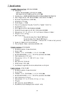
Cable

   P/N DA340-50NM


Length: 50’ 


Impedance: 50 Ohm 


RF connectors: N male and mini-UHF male factory attached 


Attenuation at 800 MHz: 2.5 dB per 30’ 


Attenuation at 1900 MHz: 5.5 dB per 30’ 


Power Supply

   P/N DP255 


Input: 100-240VAC  50/60 Hz 


Output: 5VDC  1.5A 


Mounting: Wall type 


Cord Length: 10’ (3m) 


Output plug: 5.5 x 2.5 x 11mm 


Power Cable

   P/N DP515 


Input: +/- 9VDC  to +/- 24 VDC 


Output: 5VDC  1.5A 


Center Positive, smooth cable positive 


Connector: Cigarette lighter style 


Internal fuse: 3A 


Cord Length: 76” (1.93m) 


Output plug: 5.5 x 2.5 x 11mm 


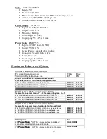
8. Antenna & Accessory Options 


Outside Dual Band Cellular Antennas 

For complete antenna specs  

Visit www.DigitalAntenna.com 

White 

P/N 

Black 

P/N 

Digital Antenna’s 500 series antennas include: 

20’ cable, mount 1”-14 threads, high-gloss finish 


2.5'  Dual Band 9dB Gain Cellular Antenna


561-CW


561-CB


4'  Dual Band 9dB Gain Cellular Antenna


563-CW


563-CB


8'  Dual Band 9dB Gain Cellular Antenna


567-CW


567-CB


Digital Antenna’s 800 series antennas include: 

female N connector, mount 1”-14 threads, high-gloss finish


2.5' Dual Band 9dB Gain Cellular Antenna 

w/ male 1"-14


854-CW  854-CB 

4' Dual Band 9dB Gain Cellular Antenna 

w/ male 1"-14


883-CW  883-CB 

8' Dual Band 9dB Gain Cellular Antenna

 w/ male 1"-14


897-CW  897-CB 


Digital Antenna’s 800 series antennas include: 

female N connector, mount wall/pole, high-gloss finish


2.5' 

Dual Band 9dB Gain Cellular Antenna

 w/ wall-pole base 

996-CW  996-CB 

4' 

Dual Band 9dB Gain Cellular Antenna

 w/ wall-pole base 

962-CW  962-CB 

8' 

Dual Band 9dB Gain Cellular Antenna

 w/ wall-pole base 

967-CW  967-CB 


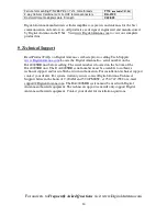
Description 

P/N 

25’ 

TM 

ULTRA low loss extension cable w/ 

connectors (attaches to included 50’ cable) 

CA340-25NM 

75’ 

TM 

ULTRA low loss cable w/ connectors 

DA340-75NM 

Summary of Contents for PowerMax DA4KSBR-50U

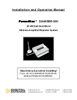
Page 1: ...allation and Operation Manual TM DA4KSBR 50U 60 dB Gain Dual Band Wireless Amplifier Repeater System Read Instruction before installing If you do not understand instructions seek professional installa...

Page 2: ...es 5 a Installation Tools 5 b Installation Procedure 5 c Electrical Power 6 d Amplifier Repeater Status 7 e In building Coverage Problems 8 f Coaxial Cable Recommendations 8 4 Home Office Installation...

Page 3: ...em complies with all FCC IC UL rules regulations and codes Follow all guidelines in the installation and instruction manual and read completely before beginning the installation procedure Do not devia...

Page 4: ...ng out of or in connection with the use inability to use or performance of the information services products and materials available from this manual These limitations shall apply notwithstanding any...

Page 5: ...rovides increased reception indoors by filtering re directing and amplifying the available signal This translates into fewer dropped calls safe clear connections and stronger signals The DA4000SBR dua...

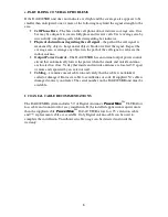
Page 6: ...ion Identify the outside antenna location If the outdoor coverage area is very poor the outside antenna should be placed on the side of the building where the signal is the strongest If the signal is...

Page 7: ...owing corrective actions The red light indicates that the inside and outside antennas are located too close to each other and need to be re located A typical installation requires that the inside and...

Page 8: ...DA4000SBR has an internal output power control circuit that automatically lowers the power when the inside and outside antenna are located too close Verify that inside and outside antennas are located...

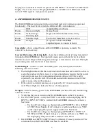
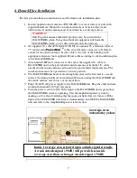
Page 9: ...ble to DA4000SBR unit on the port labeled outside antenna Attach the 18 cable attached to the inside antenna and stand to the port labeled inside antenna The inside antenna must be operated in a verti...

Page 10: ...DA4000SBR unit 3 Attach mini UHF male connector at the end of the supplied 50 cable to DA4000SBR unit on the port labeled outside antenna Attach the 18 cable attached to the inside antenna and stand t...

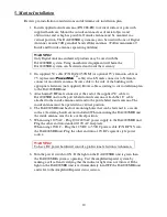
Page 11: ...at the end of the supplied 50 cable to DA4000SBR unit on the port labeled outside antenna Attach the 18 cable attached to the inside antenna and stand to the port labeled inside antenna The inside an...

Page 12: ...nside Antenna Port Mini UHF Female DC Power Coaxial ID 2 5mm OD 5 5mm center positive Indicator Multi color status indicator Power Switch Slide switch toward LED ON Outside Antenna P N 288 PB Radiatio...

Page 13: ...gloss finish 2 5 Dual Band 9dB Gain Cellular Antenna 561 CW 561 CB 4 Dual Band 9dB Gain Cellular Antenna 563 CW 563 CB 8 Dual Band 9dB Gain Cellular Antenna 567 CW 567 CB Digital Antenna s 800 series...

Page 14: ...com Locate the Digital Antenna Inc serial number on the DA4000SBR unit before calling The serial number is located on the bottom of the DA4000SBR unit The DA4000SBR serial number must be available to...

Reviews: