background image


Digital Ally, Inc. | Testing the Installation 

4-1 


Section - 4:


Testing the Installation 


1.


Insert the SD card into the DVM. 

2.


Turn the vehicle ignition switch to the ON position. The vehicle does not have to be running.  

3.


The DVM will begin the boot-up process; all 3-LEDs will flash in unison at a 1 second interval 
until boot up is complete.  

4.


Once the boot-up process is complete, the Blue LED will be lit indicating the DVM is powered on, 
is ready, and in standby mode.  

5.


Login to the DVM using the up/down arrows. The default administrator password is 111111, the 
default user password is 222222. Press the Ms button to save your entry. 


1.


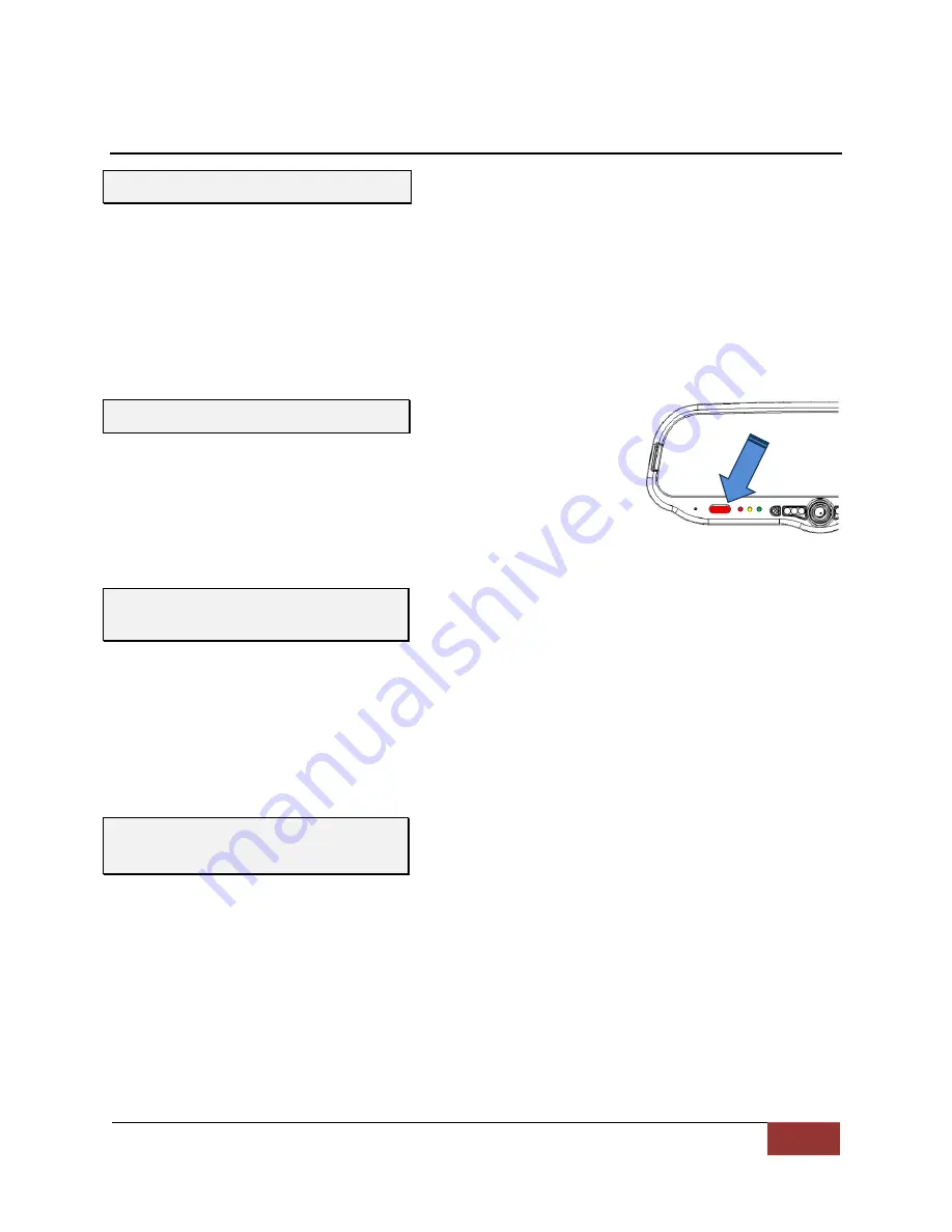
Press the RECORD button.   

2.


The Red status indicator will illuminate to indicate the manual 
event is being recorded.  

3.


After 10 seconds, press the RECORD button to stop the manual 
event record. 

4.


The Red status indicator will extinguish, indicating the DVM has returned to standby mode. 


1.


Start the vehicle and leave the transmission in Park.  

2.


Apply the brake and put the transmission into Reverse gear. 

3.


The LCD monitor will turn on and the live-video from the backup camera will be displayed. 

4.


If configured as an event trigger, the Red status indicator will illuminate indicating the back-up 
event is being recorded. 

5.


Put the transmission back into Park. 

6.


The LCD monitor will turn off. 


1.


Remove the wireless microphone from the charging cradle and turn the power switch ON. The 
Green LED should be lit solid. 

2.


Activate a connected trigger input device (such as emergency lights) to start a recording. 

3.


The Red status indicator on the DVM will flash to indicate the event is being recorded, and the 
Green LED on the wireless microphone should start blinking. 

4.


Press the record button on the DVM to stop the recording. 

5.


The Red status indicator will extinguish, indicating the DVM has returned to standby mode. 

6.


Press the REC button on the wireless microphone. The system should again start to record as 
previously in step 3. 

7.


Press the record button on the DVM to stop the recording. A power down timer will start when 
the vehicle’s ignition is turned off. 

Initial Power Up 

Record an Event 

Viewing the Backup Camera


(if 

installed)


Input Sensor & Wireless 
Microphone Tests 

Summary of Contents for DVM-LIVE

Page 1: ...system or transmitted in whole or part in any form or by any means electronic mechanical recording photocopying or in any other manner without the prior written approval of Digital Ally Inc Installati...

Page 2: ...you get started with the installation of your Digital Ally DVM Live system The DVM LiVE is designed to be easily installed into virtually any make or model of vehicle Please check the packing list aga...

Page 3: ...ER GROUND AND INPUT SENSOR CONNECTIONS 3 4 Power Cable Installation 3 4 I O Cable Installation 3 4 Determine the Device Trigger s Signal Level 3 5 Output Alarm Trigger 3 6 RJ45 to Terminal Connector A...

Page 4: ...e wiring and cabling over sharp metal edges where they may become damaged or cut To prevent electrical shorts or breakage in the wiring and cabling do not allow wiring and cabling to be pinched behind...

Page 5: ...stem 008 01455 00 Cable DWM 800 to DVM LiVE 004 09058 00 Cable Back Seat Microphone to DWM LiVE 20ft 2 5mm plug 001 00010 00 Wi Fi Assembly 006 08210 00 IO box model IFE 20 008 01388 00 Vehicle Power...

Page 6: ...Backup Camera Normal Image includes mounting h w mounting bracket 008 01390 01 Backup Camera Cable 12 2m 40 0ft 008 01382 00 008 01382 01 008 01382 02 008 01382 03 Backup Camera 25ft Extension Cable...

Page 7: ...Big Ball Mount Adapter 002 05112 00 Windshield Mount Adapter Kit Dodge Charger 001 00501 00 4 Channel Live Video Streaming Module 860 00151 00 VuVault Stand Alone Software DVD 860 00152 00 VuVault Se...

Page 8: ...yback Buttons Used to navigate the DVM menus play back videos and log into the system 9 External SD Card optional An optional external SD card can be installed behind the external SD door The SD card...

Page 9: ...3 5 DVM LiVE Rear Panel Interface Box page 3 3 I O Box to DVM Cable BTR800 Cable page 3 7 Front Camera DWM800 Wireless Microphone Connections See page 2 6 and 3 8 Main power cable connections See page...

Page 10: ...n lights are activated Connect to light bar controller Brakes Blue 3 Connect to brake pedal switch or 3rd brake light 12VDC when brake is active Siren 4 Connect to 12VDC when siren is ON Sensor 5 5 Co...

Page 11: ...the screw gently lift upward to slide mirror off of mirror mount Wedge screw less Mount Rearview Mirror Removal 1 Using a small 1 8 4 mm flat blade screwdriver insert the flat end into the opening at...

Page 12: ...e cases the mounting plate included with the DVM LiVE package must be glued to the windshield in a location that will allow proper adjustment Loctite 03346 glue is recommended Please follow instructio...

Page 13: ...n tunnel or engine firewall Mount the IO box 1 Use the IO Box to DVM cable as a gauge to estimate an appropriate location for mounting the IO box 2 Once a suitable mounting location has been identifie...

Page 14: ...e s chassis It is required that the power wire be tied in with DVM interface box connection with no obstructions to battery such as a cutoff switch or charge guard system 5 Connect the White wire to t...

Page 15: ...d of the sensor cable to access the individual wires 4 Use figure 3 5 below for wiring connections to the sensor cable and connect the external devices to the appropriate wire of the RJ 45 sensor cabl...

Page 16: ...d and the device will be powered on If the Output Alarm is not active the relay will not be energized and the device will not be powered 12V 2A max To Vehicle Battery To Pin 7 of the IF Box SENS A con...

Page 17: ...6 0050 can be used to connect the siren speaker to the interface box Follow the diagram below to install the siren interface When using the siren adapter the input sensor must be configured for a High...

Page 18: ...le to allow for movement of the mirror Pressing the Emergency button on the wireless microphone will activate the 12vdc remote accessory output signal if connected but will not trigger a record event...

Page 19: ...ntenna into the USB port on the back of the DVM Using the included double sided tape attach the antenna to an unobstructed location on the windshield below the roofline away from the GPS antenna Pleas...

Page 20: ...sible place it in a location near the roofline in which there are no obstructions between it and the sky DO NOT place the GPS antenna in close proximity of the other GPS antenna you installed previous...

Page 21: ...transmission into Reverse gear 3 The LCD monitor will turn on and the live video from the backup camera will be displayed 4 If configured as an event trigger the Red status indicator will illuminate i...

Page 22: ...indicators and clear accordingly Reset the system DVM powers up and goes directly to an event record Red LED Flashes An event record has been triggered from either an internal sensor or from an IO bo...

Page 23: ...Information 9705 Loiret Blvd Lenexa KS USA 66219 Website www digitalallyinc com Support E Mail support digitalallyinc com Sales E Mail sales digitalallyinc com Phone 00 1 913 814 7774 Fax 00 1 913 814...

Page 24: ...ng assignment assigned by administrator Signal to Input Sensor administrator use Sensor Wire Color Connection Detection Type Threshold Sensor 1 RED Reverse Gear Low to High High to Low Standard High L...

Reviews: