background image

iii

Important Safeguards

In addition to the careful attention devoted to quality standards in the manufacturing process of 
your video product, safety is a major factor in the design of every instrument. However, safety is 
your responsibility too. This sheet lists important information that will help to assure your 
enjoyment and proper use of the video product and accessory equipment. Please read them 
carefully before operating and using your video product.

Installation

1.

Read and Follow Instructions

 - All the safety and 

operating instructions should be read before the 
video product is operated. Follow all operating 
instructions.

2.

Retain Instructions

 - The safety and operating 

instructions should be retained for future reference.

3.

Heed Warning

s - Comply with all warnings on the 

video product and in the operating instructions.

4.

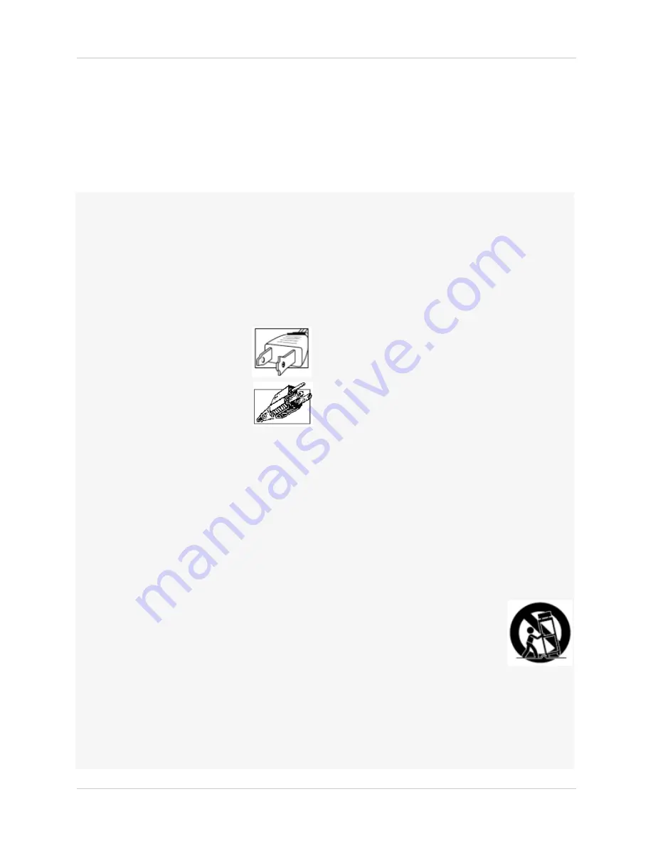
Polarization

 - Do not defeat the 

safety purpose of the polarized or 
grounding-type plug.

A polarized plug has two blades 
with one wider than the other.

A grounding type plug has two 
blades and a third grounding prong.

The wide blade or the third prong 
are provided for your safety.

If the provided plug does not fit into your outlet, 
consult an electrician for replacement of the 
obsolete outlet.

5.

Power Sources

 - This video product should be 

operated only from the type of power source 
indicated on the marking label. If you are not sure of 
the type of power supply to your location, consult 
your video dealer or local power company. For video 
products intended to operate from battery power, or 
other sources, refer to the operating instructions.

6.

Overloading

 - Do not overload wall outlets of 

extension cords as this can result in the risk of fire 
or electric shock. Overloaded AC outlets, extension 
cords, frayed power cords, damaged or cracked wire 
insulation, and broken plugs are dangerous. They 
may result in a shock or fire hazard. Periodically 
examine the cord, and if its appearance indicates 
damage or deteriorated insulation, have it replaced 
by your service technician.

7.

Power Cord Protection

 - Power supply cords should 

be routed so that they are not likely to be walked on 
or pinched by items placed upon or against them, 
paying particular attention to cords at plugs, 
convenience receptacles, and the point where they 
exit from the video product.

8.

Ventilation

 - Slots and openings in the case are 

provided for ventilation to ensure reliable operation 
of the video product and to protect it from 
overheating. These openings must not be blocked or 
covered. The openings should never be blocked by 
placing the video equipment on a bed, sofa, rug, or 
other similar surface. This video product should 
never be placed near or over a radiator or heat 
register. This video product should not be placed in a 
built-in installation such as a bookcase or rack 
unless proper ventilation is provided or the video 
product manufacturer’s instructions have been 
followed.

9.

Attachments

 - Do not use attachments unless 

recommended by the video product manufacturer as 
they may cause a hazard.

10.

Camera Extension Cables

 – Check the rating of 

your extension cable(s) to verify compliance with 
your local authority regulations prior to installation.

11.

Water and Moisture

 - Do not use this video product 

near water. For example, near a bath tub, wash 
bowl, kitchen sink or laundry tub, in a wet 
basement, near a swimming pool and the like. 

Caution

: Maintain electrical safety. Powerline 

operated equipment or accessories connected to 
this unit should bear the UL listing mark of CSA 
certification mark on the accessory itself and should 
not be modified so as to defeat the safety features. 
This will help avoid any potential hazard from 
electrical shock or fire. If in doubt, contact qualified 
service personnel.

12.

Accessories

 - Do not place this 

video equipment on an unstable 
cart, stand, tripod, or table. The 
video equipment may fall, causing 
serious damage to the video 
product. Use this video product 
only with a cart, stand, tripod, 
bracket, or table recommended by the 
manufacturer or sold with the video product. Any 
mounting of the product should follow the 
manufacturer’s instructions and use a mounting 
accessory recommended by the manufacturer.

Summary of Contents for VBAY3HD

Page 1: ...Copyright 2009 Digimerge Technology Inc www digimerge com Right For Business INSTRUCTION MANUAL English Version 1 0 HARD DRIVE EXPANSION BAY DESIGNED FOR THE DIGIMERGE BLADE VBAY3HD...

Page 2: ...REFER SERVICING TO QUALIFIED SERVICE PERSONNEL The lightning flash symbol within an equilateral triangle is intended to alert the user to the presence of uninsulated dangerous voltage within the produ...

Page 3: ...ced by your service technician 7 Power Cord Protection Power supply cords should be routed so that they are not likely to be walked on or pinched by items placed upon or against them paying particular...

Page 4: ...ent fire electric shock or other hazards 16 Safety Check Upon completion of any service or repairs to this video product ask the service technician to perform safety checks recommended by the manufact...

Page 5: ...t the user follows the guidelines in this manual to avoid improper usage which may result in damage to the unit electrical shock and fire hazard injury In order to improve the feature functions and qu...

Page 6: ...pansion capability total of 3 hard drives not included Mirroring capability duplicates data on your Blade providing secure data redundancy Ultra slim stackable design Rugged metal enclosure Dual exhau...

Page 7: ...n Bay to Record Events 6 Setting Up The Expansion Bay In Mirror Mode 7 How the Mirroring Sequence Works 7 Error Messages 8 Restarting The Expansion Bay 8 Upgrading The Hard Drive 8 Remove The Casing 8...

Page 8: ...viii...

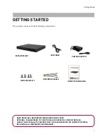
Page 9: ...ER ADAPTER INSTRUCTION MANUAL USB CABLE GROUNDING CABLE HDD SCREWS X12 HARD DRIVE SIZE HARD DRIVE CONFIGURATION MAY VARY BY MODEL PLEASE REFER TO YOUR PACKAGE FOR SPECIFIC CONTENT DETAILS CHECK YOUR P...

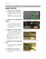
Page 10: ...USB cable from the rear panel of the expansion bay to the rear panel USB port on the Blade TIP The bottom USB port on the rear panel of the Blade offers faster transfer rates NOTE It is highly recomme...

Page 11: ...th longer USB cables 5 Ground Port Grounds the unit from electric shock Always ground the unit to prevent damage 6 DC12V Power Port Port for 12V power supply included STACKING THE EXPANSION BAY The ex...

Page 12: ...upgrade Once the firmware upgrade is complete the system prompts you with the message PLEASE RECYCLE DVR POWER 6 Turn off the Blade for five seconds then turn it back on The system flashes a blue prom...

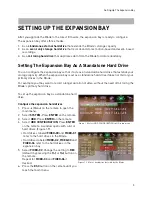
Page 13: ...xample you may want to record a longer duration of video without the need of mirroring the Blade s primary hard drive To set up the expansion bay as a standalone hard drive Configure the expansion har...

Page 14: ...on the remote 3 Select HDD Press ENTER on the remote 4 Select HDD CONFIGURATION Press ENTER on the remote A window opens with a list of hard drives Figure 2 1 Hard drives labeled FIXED 00 and FIXED 01...

Page 15: ...in the third hard drive HD3 in illustration copies data from the Blade When the third hard drive HD3 in the expansion bay is full the first hard drive HD1 begins to copy data from the Blade This proce...

Page 16: ...st restart the Blade in order to detect the expansion bay hard drives To restart the expansion bay unplug the power cord from the rear panel Wait five seconds before powering back on Always set up the...

Page 17: ...erneath the unit Bay 1 Bay 2 Bay 3 Figure 2 8 Internal layout of expansion bay with three hard drives installed Note that the hard drive in Bay 1 is upside down This is the correct way of installing t...

Page 18: ...en the four bracket screws to secure mounting bracket in place Figure 3 0 Install the two mounting brackets on the side of the hard drive NOTE The screws that mount the hard drive to the bracket are l...

Page 19: ...e unit 2 Gently lift the hard drive out of the bay and disconnect the SATA power and SATA data cable from the hard drive 3 Remove the screws securing the mounting brackets Figure 3 3 Lift the hard dri...

Page 20: ...Sata connectors are designed to connect one way only The connector with the flat red cable is the data connector The wider connector with the red and black wires is the power connector Hard Drive Rot...

Page 21: ...1 7A peak Read Write 12V 0 8A typical Power Consumption with 2 HDs installed Start 12V 3 0A peak Read Write 12V 1 2A typical Power Consumption with 3 HDs installed Start 12V 4 4A peak Read Write 12V 1...

Page 22: ...14 Appendix A VBAY3HD Specifications Appendix A cont d Accessories Ground Conductor Grounding Cable AC Adaptor 12 5A with AC Cord Screws 5W 32 32 for HDD Installation USB 2 0 Cable...

Reviews: