background image

35


IO

S

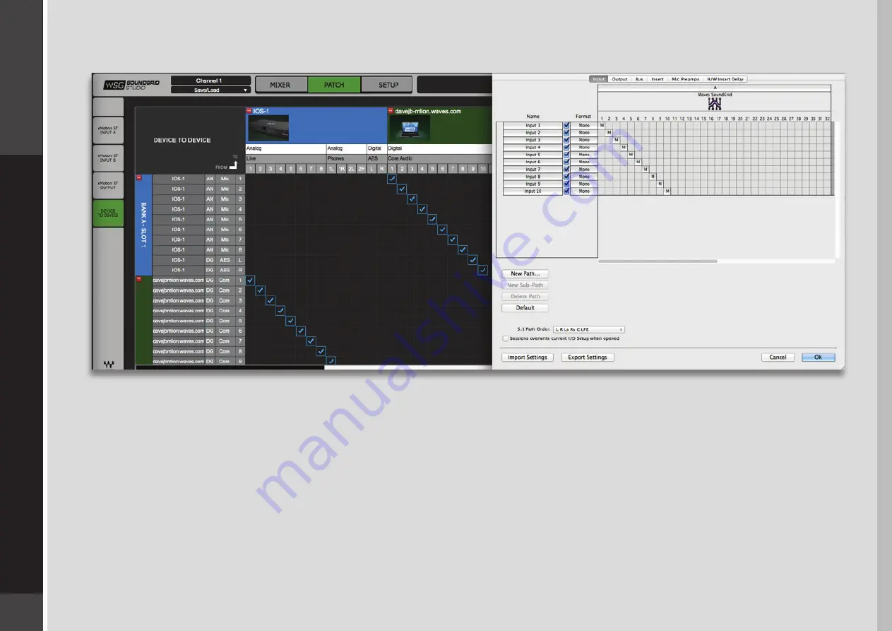
Note the relationship between the SoundGrid Studio Patch page and the DAW I/O Setup page.

In the Patch page (left), IOS analog channels 1–8 are patched to driver channels 1–8, and IOS AES L and R are patched to driver 
channels 9 and 10. The arrow on the upper left of the Patch indicates that signal flows from the IOS to the driver.
Now look at the DAW I/O. The 10 driver channels appear at the top, and are patched to DAW input channels 1–10.

You may find it convenient to rename the channel path names in your DAW to reflect what is patched to the driver channel in the 
SoundGrid Studio Patch page. This will simplify setting up sessions when you have multiple devices or customized patching.

Summary of Contents for IOS

Page 1: ...IOS ...

Page 2: ... 1 One Computer with a DiGiGrid IOS 9 3 2 Adding More I Os to Your System 10 3 3 Multiple Computers with a Single DiGiGrid IOS 11 3 4 Advanced Network Multiple Computers and Multiple I Os 12 4 Software Setup And Controls 14 4 1 Device Firmware 17 4 1 1 Resetting the Unit 17 4 2 Identifying a Device from the SoundGrid Studio Device Rack 17 5 Control Panel 18 5 1 Controls Page 20 5 1 1 Top Bar 21 IO...

Page 3: ...erver 29 6 1 1 eMotion ST mixer 29 6 1 2 StudioRack 30 7 Moving Audio in a Soundgrid Network 31 7 1 Using an I O Device with a DAW 32 7 2 Patching I O to Driver and Driver to I O 33 7 3 eMotion ST Mixer Patching 36 7 4 Device to Device Patching 37 7 5 Headphone Patching 38 8 Using the IOS with Midi 39 9 Technical Specifications 40 9 1 Installation Notes 42 ...

Page 4: ... controllers and servers and patches audio throughout the system Any user anywhere on the SoundGrid network has access to all available network I O devices Adding a SoundGrid DSP server enables processing recording and monitoring DiGiGrid IOS is an audio interface for native DAWs and Waves SoundGrid applications that run on a SoundGrid network It has eight mic line inputs and 8 line outs along wit...

Page 5: ...ailable at Waves website IOS SoundGrid Studio software installed on the host computer Cat 5e or Cat 6 Ethernet cables 1 2 Registration To download IOS software you will need to register your device at www digigrid net or www waves com You must know the serial number of your IOS in order to register it so sign up before you mount it in a rack The serial number appears on a label on the bottom of th...

Page 6: ...dioRack a software plugin rack or chainer that hosts up to eight plugins and can move their processing from the DAW to the SoundGrid server eMotion ST a software mixer that provides low latency plugin processing and monitor mixing 1 4 Licenses DiGiGrid Native I O devices do not require a license to operate in a SoundGrid network However certain advanced features such as using StudioRack and eMotio...

Page 7: ... signal present Green signal present 48v phantom power Orange ON Network status indicator Blue Device recognized by the SoundGrid network Red Device not recognized by the SoundGrid network Yellow Updating White Unit malfunction e g firmware did not load properly unit did not boot properly Cycling through colors This LED is also used to identify the unit from the control panel Power switch indicato...

Page 8: ...d to Waves applications and to DAWs Digital and clock connections software selected Clock in and out BNC connectors for external Word Clock S PDIF in and out RCA connectors AES in and out XLR connectors Analog connections 8 mic line inputs combo XLR TRS connectors 8 line out TRS connectors Alt line out DB25 8 channel balanced connector See connection diagram in IOS specifications section 7 8 9 10 ...

Page 9: ...x your setup is connecting an IOS involves only one cable an Ethernet Cat 5e or Cat 6 3 1 One Computer with a DiGiGrid IOS This is the most basic studio configuration It includes a host computer with a native DAW and a single DiGiGrid IOS that connects microphones instruments headphones and monitors to the SoundGrid ASIO Core Audio driver This driver controls the network and all its devices The bu...

Page 10: ...through the same Ethernet cable This means of distributing clock is called Sync over Ethernet SoE and is used between all SoundGrid devices To clock the entire network to an external clock source such as house sync use Word Clock or Digital In as clock master for the IOS If the IOS is the SoE master then the entire network will be locked to this external source Adding more SoundGrid compatible I O...

Page 11: ...computer can control the I O Any native DAW or combination of different native DAWs can be a part of this network so each computer must have the IOS software installed Each of the additional computers is connected to the DiGiGrid IOS s Ethernet switch via a single Cat 5e or Cat 6 Ethernet cable Alternatively you can use an approved external 1GB Ethernet switch Ethernet Analog Clock External Clock ...

Page 12: ...HD system with the DLS providing a built in SoundGrid DSP server for plugin processing Another DAW system with an IOS can be used as a second control room system an editing room DAW or a recording station for the voiceover booth A DiGiGrid IOX provides a live room or voiceover booth with 12 analog inputs and 4 separate headphone outs A DiGiGrid MGB MGO unit connects this network to a MADI source f...

Page 13: ...n Clock Mode setting in the DLS DLI control panel Primary Port In Expansion Port Out DigiLink Interface WC Loopsync DL1 Ethernet DL2 A B DL1 Ethernet DL2 MADI Matrix 1 2 1 2 DiGiGrid DLS DiGiGrid IOX DiGiGrid IOS DAW SG Studio DiGiGrid MGB MGO DiGiGrid DLI ...

Page 14: ...es between devices and provides access to device control panels To maintain network effectiveness the SoundGrid Studio Application always runs in the background Bring SoundGrid Studio to the front by clicking on the SoundGrid icon in the Mac Top Bar or the Windows System Tray When SoundGrid Studio opens you will see the System Inventory page part of the Setup section Mac PC ...

Page 15: ... click SCAN When configuration is complete close the window If there s still a problem you can use the System Inventory page to assign devices control the network and manage clock To learn how to use this page please refer to the SoundGrid Studio Application user guide SoundGrid Studio uses Ethernet to stream audio between devices on a SoundGrid network Clock synchronization is also carried over E...

Page 16: ... coaxial MADI interface In this image the IOS is grayed out and therefore unavailable since it is already claimed in this case by you The new device is visible in the rack slot Unless changed by the user it remains a clock slave and is colored green Use the same menu to change the clock master assignment from one device to another or to remove the device from the rack slot ...

Page 17: ...of the hardware and then offer options Do not disconnect the device or turn off the computer until you see Done After updating turn the IOS off and back on to reset the device 4 1 1 Resetting the Unit If an unsuccessful firmware update results in the IOS no longer being recognized by MultiRack or SoundGrid Studio the IOS device is not showing in the inventory panel you can use the Reset button to ...

Page 18: ... in the SoundGrid Studio Device Rack From the IOS Control Panel you can manage Clock settings source sample rate type clock status Microphone preamp controls input gain phantom on off Output levels Sample rate conversion of digital inputs In addition there are input and output meters ...

Page 19: ... in a rather psychedelic manner You can save and load presets of device settings A saved preset includes all Clock and Control panels parameters Use IOS presets to use on future sessions or copy them to another computer to duplicate a configuration To save a preset click the SAVE button and choose a name and path Loading a saved preset is equally obvious Device presets are also saved as part of a ...

Page 20: ...ges are used to set up and manage the IOS 5 1 Controls Page This is where you configure the inputs and outputs of the IOS Mic preamps line inputs and outputs digital I O level control and metering all of the things you d expect from a top end I O The Controls page is divided into four sections Top Bar Analog section Digital section Focus section Analog and Digital input and output levels are contr...

Page 21: ... Focus section Analog Input Controls Use the Focus section to set preamp levels and turn the 48v phantom on and off The long meters range from 80 dBFS to 0 dBFS Mic knob gain range 0 dB to 52 5 dB in 7 5 dB steps Line knob gain range 0 dB to 52 5 dB in 7 5 dB steps Fine knob digital gain range 0 dB to 7 dB A clip indicator holds for two seconds or for as long as clipping persists Peak hold persist...

Page 22: ...rity reverse button Stereo channels have two Buttons are latching and are colored green when engaged Input Polarity Controls input level from digital sources Separate controls for L R when input is stereo Digital Input Trim This allows you to control preamps on the fly without leaving your monitor mixer eMotion ST also provides a digital trim for incoming digital signals Refer to the eMotion ST us...

Page 23: ...trols In addition to meters and clip and peak indicators which are identical to the input controls there is a Headroom switch that provides a 10 dB pad Presence of the 10 dB pad on an analog output is indicated by a blue light ...

Page 24: ...tween AES EBU and S PDIF This choice is reflected in the Top Bar illustration Use the SRC button to enable input sample rate conversion When SRC is selected IOS will convert incoming digital stream to the sample rate of the clock that the device is locked to A yellow light on a channel button indicates that sample rate conversion is active for that channel ...

Page 25: ...able The threshold can be set to 0 dB 1 dB 2 dB or 3 dB This setting is global not channel specific When Clip Indication Threshold is set this behavior affects level indication for all channels input and output Additionally each channel button analog or digital input or output has a small level meter that indicates signal and provides a rough idea of level A red light on the channel button indicat...

Page 26: ...side of the page status indicators are on the right SOURCE sets the clock source Internal The interface itself provides the clock External WC Clock is provided by an external device via the IOS Word Clock Input connector Sync over Ethernet Word clock is transmitted between SoundGrid devices using Ethernet Digital IOS clocks to an incoming digital stream ...

Page 27: ...his may differ from the choice made in the Source menu SOE Indicates whether this IOS is the master or a slave in the SoundGrid network This mirrors the status information in the SoundGrid Studio Device Rack When the IOS is a slave in the SoundGrid network you will likely sync it to the SoundGrid network clock via SoE Even when IOS is an SoE slave you can lock it to an external clock source For ex...

Page 28: ...r computer while keeping the server on your own host or to use a server from elsewhere on the network To assign free or rename a server click on the arrow to reveal the list of available servers select a server from the list and remove or assign the server A server cannot be shared by multiple SoundGrid host applications such as SoundGrid Studio or MultiRack Within a SoundGrid network only one com...

Page 29: ...nitoring while recording The eMotion ST mixer enables you to create personalized monitor mixes with plugin processing done pre post or in parallel with your DAW eMotion ST combines 8 channel inputs with up to 64 StudioRack plugins Each input or StudioRack channel can be sent to aux tracks or a main mix You can set up and control the IOS preamp from eMotion ST so you never have to leave the mixer t...

Page 30: ...cessors with limitless parameters and flexible signal flows which are easily inserted into any track of the session When part of a SoundGrid network with a DSP server such as DiGiGrid IOS StudioRack can shift plugin processing away from the local CPU and direct it to the SoundGrid DSP server StudioRack works in conjunction with the eMotion ST mixer to create numerous personalized monitor mixes tha...

Page 31: ...hink about patching When you first set up a SoundGrid network or change its physical inventory the Wizard automatically sets up your devices and establishes the patches Still you should know how to patch between devices drivers and applications Then you can take advantage of the flexibility of a SoundGrid network There are three types of SoundGrid Patch page connections Patch I Os to drivers in or...

Page 32: ...river then select the correct driver in your DAW as the playback engine Selecting the Number Of Channels When you configure your host application you can allocate between 32 and 128 driver channels This is done in Rack B of the Setup page The number of channels you select here is reflected in the Patch page fewer allocated channels means fewer channels visible Pick a number that only slightly exce...

Page 33: ...ce tab All device and driver channels are shown along both the horizontal and vertical axes To make a standard ascending patch connection draw the cursor in a diagonal line as shown below To create a customized patch click on individual cells There are many ways to patch devices but normally IOS inputs are patched to the ASIO Core Audio inputs for recording For playback the patches are opposite un...

Page 34: ...s themselves What these channels are ultimately connected to is determined in the Patch page of the SoundGrid Studio Application Selecting the Driver in the DAW When a DAW is part of a SoundGrid network the SoundGrid ASIO Core Audio driver must be its playback engine Choose Waves SoundGrid from among your playback engine options ...

Page 35: ...row on the upper left of the Patch indicates that signal flows from the IOS to the driver Now look at the DAW I O The 10 driver channels appear at the top and are patched to DAW input channels 1 10 You may find it convenient to rename the channel path names in your DAW to reflect what is patched to the driver channel in the SoundGrid Studio Patch page This will simplify setting up sessions when yo...

Page 36: ...o learn more about patching between devices or to and from the eMotion ST mixer please refer to the SoundGrid Studio Application user guide A few things to remember about the Patch page All available devices and driver channels will appear in the patch The number of channels depends on devices and connections Patch direction is indicated by an arrow on the left side of the patch Establish a patch ...

Page 37: ...long both the horizontal and vertical axes There are many ways to patch devices but normally IOS inputs are patched to the ASIO Core Audio inputs for recording For playback the patches are opposite unless you choose to patch to the eMotion ST mixer for monitor mixing For further details refer to the SoundGrid Studio Application user guide ...

Page 38: ...38 IOS 7 5 Headphone Patching IOS has two independently adjustable headphone jacks These appear on the Patch page after the 8 I O channels Adjust headphone levels on the IOS front panel ...

Page 39: ...device s MIDI ports the other is for StudioRack this is explained in greater detail in the StudioRack manual To activate MIDI ports open the SoundGrid Studio Application Go to I O Rack A and locate the IOS that you want to assign From the drop down menu choose Assign to SoundGrid MIDI Driver In the host select the port for MIDI in and out Waves SoundGrid Device I O ...

Page 40: ...dGrid ports RJ45s USB port emergency port to boot server support function Reset switch 2 headphone outputs with analog level knobs range Off to 15 dB Settings for different broadcast level formats via jumpers on all analog I Os Internal SoundGrid DSP server Intel i3 Analog Inputs specifications Input Impedance Mic 2K5 Line 8K0 Gain Range Mic 0 dB to 52 5 dB in 7 5 dB steps Line 0 dB to 52 5 dB in ...

Page 41: ... Typically 0 01 10 dB Output 1 kHz IOS Analog Connectors DB25 8 channel balanced connector AES59 2012 XLR connectors Phase Termination Point Positive Pin 2 Negative Pin 3 Signal Ground Pin 1 Chassis Ground Case 1 2 3 4 5 6 7 8 G C H G Ground C Cold H Hot G C H G C H G C H G C H G C H G C H G C H 13 25 24 23 22 21 20 19 18 17 16 15 14 12 11 10 9 8 7 6 5 4 3 2 1 TRS connectors Phase Termination Poin...

Page 42: ...use in ambient air temperature of up to 35 C Operation in higher temperatures should be avoided A 1U space should be left above and below the unit to prevent heat transfer from adjacent equipment if this generates heat above 35 C At least 75 mm 3 inches should be allowed to the sides of the unit to allow ventilation At least 75 mm 3 inches of free air should be left at both the front and the rear ...

Reviews: