digico SD7 Operation Manual Download Page 7

SD7 - Getting Started

1-3

1.3.2 Layers and Banks .................................................................

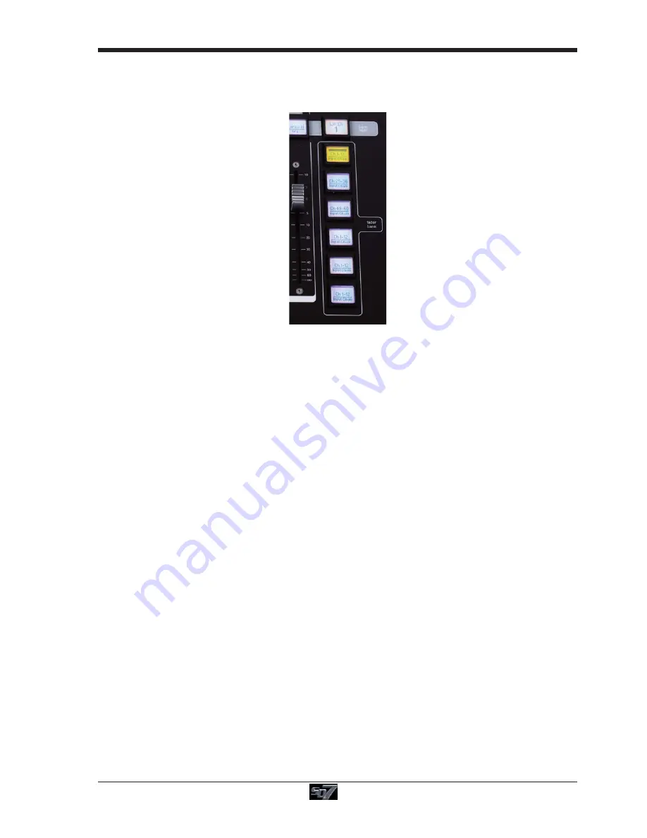
The SD7's worksurface is divided into Layers and Banks. Each Bank contains twelve channels, and the channels which are
currently active on the control surface are defined using the fader bank and bank layer buttons to the right of the Channel Strip
section’s faders:

A ‘bank’ is a set of twelve faders, and a ‘layer’ contains up to six ‘banks’. There are up to 3 ‘layers’ in each section of the desk,
allowing up to 216 channels to be accessible on each worksurface section.

Pressing the bank layer button, located above the fader bank buttons, toggles between layers.

To access a bank of faders within that layer, press the appropriate fader bank button. To switch all three sections of the
console to the same bank level, press and hold one of the fader bank buttons.

The specific channels which are contained within each Bank is defined in the Layout  >  Fader Banks display. By default, the
Input channels will be assigned to Layer 1 on the left and right sections of the console. The different output channels will be
assigned to Layer 2 and also to the upper centre section. Control Groups will be assigned to the lower centre section. These bank
assignments can be customised by the user and saved in a session at any time. Holding any bank or layer button down for a
couple of seconds will switch all 3 worksurface sections to the same bank level or layer.

1.3.3 Using the Control Surface ....................................................

There are two main ways in which all of the functions of the SD7 are accessed:

1. The touchscreen display, which can be controlled directly using a finger, or by using the keyboard and mouse
2. The physical encoders, switches and faders.

Note that when touching the screen directly, you may find it easier to use a finer point than your finger.
However, in order to prevent damage to the screen, it is important that you only use devices specifically
designed for touching screens (such as a pda stylus), and that you never press down hard on the screen.

A number of functions can be accessed in different ways, allowing users to operate the console using whichever interface they
prefer. This manual will describe accessing on-screen functions by touching the screen directly and not by using the mouse.

All of the physical controls found in the centre section are described in full within the relevant section of the manual and many
require no further introduction.

The Master screen has a row of grey buttons accross the top, which are used to access a range of configuration displays.
Pressing these buttons opens either a further drop-down sub-menu or a pop-up display. If a drop-down menu is opened, pressing
on one of its entries will open a pop-up display. The buttons lighten to indicate that their sub-menu or pop-up display is open. A
number of the buttons within each pop-up display generate further pop-ups.

Generallly, buttons within the pop-ups are coloured grey when their function is inactive, switching to a colour when their function
is active. Pressing on a text box opens a numeric or QWERTY keypad which can be operated directly by pressing the screen or
via the console’s external keyboard.

Pop-ups are closed by pressing the box in the top right-hand corner of the pop-up, marked CLOSE or CANCEL (or by pressing
CAN on keypad pop-ups).

Summary of Contents for SD7

Page 1: ...SD7 Operation Manual 0 1 User Manual Getting Started To be read in conjunction with the SD Series Software Reference User Manual Version D for Software Versions 4 0 680 ...

Page 2: ...gico UK Ltd Registering the Product is deemed an acceptance of the terms and conditions in this agreement 3 The Product and its licence are not transferable and the Customer is not permitted to onward license to any third party The Cus tomer indemnifies Digico UK Ltd against any and all claims and actions arising from third party use of copies of the Product made by theCustomer 4 The Customer agre...

Page 3: ...w 1 8 1 5 3 Audio I O Overview 1 9 1 5 4 Opto V220 DiGiRacks and Opto V221 SD Racks 1 10 1 5 5 Automatic Conforming 1 10 1 5 6 Network Mirroring 1 10 1 5 7 Single SD Console System 1 11 1 5 8 Manual Conforming of Racks 1 12 1 5 9 Rack Sharing 1 13 1 5 10 Assigning Faders to the Worksurface 1 14 1 6 Saving and Loading Sessions 1 15 1 7 Audio Sync 1 16 1 8 Routing Basics 1 17 1 8 1 Selecting Inputs ...

Page 4: ...SD7 Operation Manual 0 4 1 12 Multi channel formats 1 24 1 13 Solo Setup 1 25 ...

Page 5: ...rs The console s buss architecture is dynamic and can support mono stereo LCR LCRS and 5 1 configurations Multiple console setups can provide Front of House and Monitoring with shared stage racks and gain tracking Remote control of one console from another console or from a laptop computer 1 2 Manual Overview This manual provides an overview of the desk and describes some of the basic operating pr...

Page 6: ...itch Assignable Rotary Scrollers Meter View Switch Channel Inserts A B On Off Direct Out On Off 4 Band Dynamic Parametric EQ High and Low Pass Filters Multiband Dynamics Thresholds On Off Joystick Dedicated Aux Rotaries Hard Mute Full Safe Channel Scroll Undo Redo Layer Switch Channel Fader Banks Centre Section Rotary Resolution Screen Scroll Channel Faders Mutes Graphic EQ Controls LCD Function B...

Page 7: ...ich can be controlled directly using a finger or by using the keyboard and mouse 2 The physical encoders switches and faders Note that when touching the screen directly you may find it easier to use a finer point than your finger However in order to prevent damage to the screen it is important that you only use devices specifically designed for touching screens such as a pda stylus and that you ne...

Page 8: ...ll of the controls for that channel which are not displayed within the channel strip itself can be accessed via secondary pop ups displayed by touching inside the relevant area of the channel These pop ups include controls such as input and output routing and signal processing parameters A number of the physical rotary encoders on the control surface can be assigned to different on screen pots In ...

Page 9: ...Switching of LR or LCR panning 4 Fine adjustment of Delay settings on output channels 2nd function is indicated by a green 2nd Function display appearing in the bottom left hand corner of the screen as well as by the 2nd function button lighting with a ring of green The Option All button has 2 main functions 1 When pressed and released any channel that is a member of a gang will be temporarily iso...

Page 10: ...ustomised by the user and saved in a session at any time Holding any bank or layer button down for a couple of seconds will switch all 3 worksurface sections to the same bank level or layer The controls on each different type of output channel are identical but an input channel has a number of additional features Input Module Touch to Expand Analogue Gain Digital Trim Phase Gain Tracking Main Alt ...

Page 11: ...it was last Shut Down To Shut Down the console press the System Shut Down button and wait until you receive a message saying that it is safe to switch the power off The SD7 worksurface has 12 analogue I O and 12 AES I O on its rear panel referred to as Local I O and additional I O is supplied in the form of remote Racks which can each accommodate up to 56 inputs and 56 outputs in different formats...

Page 12: ...tarting a new session from scratch it is important to decide how many of each type of channel is required While changes to session structure can be made once a session has been started it is best to try and set these parameters before configuring the session The structure will set items such as the number of input channels the number and type of aux channels group channels and matrix channels avai...

Page 13: ...l channels you have allocated will not be placed on the worksurface and need to be manually assigned to faders If however you restructure a session with Rebuild Banks either Horizontally or Vertically enabled the worksurface will be built with all channels available on the worksurface in a default layout Rebuilding horizontally will result in input channels being spread accross the top layer of bo...

Page 14: ...are present close the Diagnostics panel Irrespective of the type of rack being used the system needs to be conformed This involves the console checking the type of racks connected and their I O capability There are three levels of automatic conforming globally using the red Conform All Ports button in the bottom left of the window on a rack by rack basis using the conform rack button just below th...

Page 15: ...TWORK window and you should see yellow OK lights against Engine A and Engine B This indicates that the network has connected the two engines but they are not yet mirrored In order to mirror the two Engines they need to be running the same session The way to achieve this is to load the session into the A Engine then transfer it to the B Engine using the Network panel buttons as follows 1 Ensure you...

Page 16: ...s Red then there is a mismatch and the error should be corrected by selecting the correct card type Copying Audio and Listening to Copied Audio MADI Recorder Setup Audio from a Rack can be copied to the MADI Port Output by selecting the incoming Port in the Ports list and using the Copy Audio To drop down menu For example if you want to copy the Rack Audio Inputs to a recorder connected over MADI ...

Page 17: ... with the rack and therefore any adjustment of input gain or 48V switch will have no effect on the rack settings Receive Only The SD7 will receive the rack s existing settings but will not be able to control the gain etc on the racks Full Control The SD7 will send its settings to the racks and change them accordingly Sharing is configured in the Rack Sharing area found in bottom right hand corner ...

Page 18: ... channels that you wish to assign Now press the first channel that you wish to assign on the Layout Channel Faders list on the Master screen Consecutive channels will be assigned to the worksurface for each LCD button that is in Assign mode Now press the LCD Function button again and return to the standard mode by pressing the LCD button labelled Solo Note that column widths can be adjusted by dra...

Page 19: ...in D Projects Note that column widths can be adjusted by dragging their borders within the title row To return all col umns to their default widths press RESET WIDTHS in the top left hand corner of the window 1 6 2 Save Session This button which is found above the Save As New File button will save the existing session in the same location and under the same file name as it was previously saved or ...

Page 20: ... any console s are connected to racks with optical fibre then all console engines should be set to Optocore as their sync source Example Clocking from Optocore 96kHz There are also times when the SD7 needs to be clocked externally The Audio Sync panel allows you to control external synchro nisation The SD7 will clock from the following sources Word Clock AES EBU Video Reference MADI Optocore In th...

Page 21: ...ing assigned within the display the port and signal group columns containing the current assignment will be half lit Each output can only have one channel routed to it The outputs that are currently in use by another channel display in blue text If you attempt to route a different channel to an output which is already in use a confirmation box appears indicating which channel is already using it a...

Page 22: ...For example Channels 1 to 8 direct outputs can be routed to Rack 1 Line outs 1 to 8 respec tively by routing Channel 1 s direct out to Rack 1 Line out 1 and allowing the ripple channels function to route Channels 2 8 automatically The number of channels to be rippled is defined either by selecting the appropriate grey numbered button or by selecting the keyboard button to the right of the numbered...

Page 23: ...ions panel and set the Auto Expand EQ option to Yes Each band s response can have one of two characters precision and classic These can be switched for all bands using the precision and classic buttons or on individual bands using the 2nd function of the bell hishelf buttons To access the Dynamic control touch the left arrow symbol on any EQ band Touching the normal EQ response graph will show an ...

Page 24: ... is shown by the Status Display Click on the dynamics mode select button on the left of the display to access the 3 dynamics bands Each band includes all of the parameters as those found in the single band compressor The link function remains available for the whole compressor and is not assigned to any band The bands can be switched on individually using the on buttons in the left hand side of ea...

Page 25: ...own in steps of 4 Assigned Control LCD Hold touch screen to Assign Assignable Aux Send Controls Touch screen to select Dedicated Aux Send Controls and WorksurfaceScroll buttons It is also possible to show all of the aux sends for a channel in a single display and assign them to the 36 rotaries beneath the screen This is done by assigning the required channel to the aux controls the assigned auxes ...

Page 26: ...ple above has the Master Stereo Buss routed to the inputs of Matrix 1 and Matrix 2 Labelled as PA Left PA Right By adjusting the crosspoint levels you can change how much of each side of the Master buss is fed to these Matrix Channels There are three modes of level adjustment multi single and all Multi active when no other mode is selected Touch one or more level knob on screen then adjust using t...

Page 27: ...lease the JOIN LEAVE button List of members Press Join Leave button on required CG channel Press Channel LCD buttons to assign members A list of all the connected channels and their names is displayed above each Control Group display You can also clear all the channels from a Control Group by pressing Clear When a channel is a member of a Control Group its own controls can still be adjusted indepe...

Page 28: ...pear against each component Each channel can then be left on the worksurface or removed using the buttons towards the base of the display Finally touch OK to close the display to link the channels together Note that you can also create Multis on a blank layer by selecting the Create Multi LCD function on the Layer you wish to use then pressing the LCD button for the required channel strip The incl...

Page 29: ...Off Clear multi single solo mode pfl afl solo mode The following functions are available independently for each solo buss Mono Stereo Surround Switch No Solo source routing The source for solo buss when no channel is in solo mode Note that the No Solo source does not show on Solo meters Insert Point with both internal and external routing capability Direct Out routing eg for feeding a wedge Assign...

Page 30: ...SD7 Getting Started 1 26 ...

Reviews: