WR41 Series Installation Guide
10
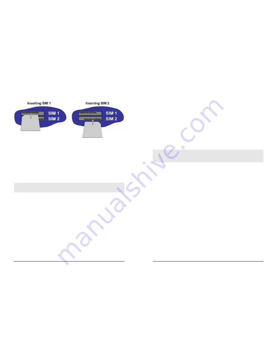
In both cases, the end of the SIM card with the chamfered corner should be inserted first.
For SIM 1 the contacts should be face down. For SIM 2 the contacts should be face up.
Step 2 – Fitting the wireless antenna(s)
The router is supplied with a “stub” antenna suitable for with the model you have ordered.
Alternatively you may have ordered a different type of antenna separately. In either case
this should be screwed onto the SMA connector labelled ANT.(MAIN) on the rear panel.
If you have a WR41-U or WR41-C, the unit will come with two antennas. When both of
these are fitted the operation over the wireless network may be improved, especially in
areas of low signal strength. This is called “diversity” mode. The second antenna should
be screwed onto the SMA connector labelled ANT.(AUX.) on the rear panel.
Note: If you use antennas other than the stub antennas supplied as standard (e.g. two
wall-mount antennas), the separation between the two should be no less than the
separation between the two associated connectors on the rear panel of the unit.
Step 3 – Connecting the LAN cable
Plug one end of one of the supplied 2 metre CAT5 STP cable into the RJ45 socket
labelled LAN 0. Plug the other end into the LAN socket on your PC or notebook.
Step 4 – Connecting the serial cable
For connection to a serial terminal device, an RJ45 to 9-way D-type adapter is required
and can be purchased separately. Connect the RJ45 plug on the adapter into the socket
labelled ASY 0 on the rear panel of the router. A suitable serial cable can then be used to
connect the router to the serial port on your terminal.
Step 5 – Connecting the power supply
Plug the jack plug on the mains adapter into the socket labelled 5V DC. When power is
first applied, the ON indicator will illuminate and the unit will initiate a series of diagnostic
self-tests. During this process one or more of the other indicators, will flash to show that
the unit is busy. When the flashing stops, the unit is ready to use.
The unit is now ready to be configured.
WR41 Series Installation Guide
11
3 Configuration
Once the router has been installed and powered up, you must now configure it to
communicate with your network and the Internet. The easiest way to do this is to use the
Sar/OS Connection Wizard, available from the Digi website.. The Sar/OS Connection
Wizard will take you step-by-step through the process of configuring the router.
You can choose to just configure the unit’s Ethernet port (so that you can connect to it
over your LAN in order to configure it fully), or you can use the wizard to configure the
unit’s Ethernet port, and at the same time connect it to your wireless network.
Using the wizard means that you will not have to change the IP address of your PC.
Rather, you will be able to change the IP address of the router to match the subnet your
PC is already on.
Note: The default IP address for the LAN 0 port is 192.168.0.99, with a Class C subnet
(255.255.255.0). Setting your PC’s IP address to one on the same subnet (192.168.0.*)
will enable you to connect to the unit’s Web interface. You will then be able to configure
the unit manually.
Step 1 – Install the Connection Wizard
Download the connection wizard from the Digi website and install the software on your
PC.
Step 2 – Run the Wizard
Once the wizard has been installed on your PC, run it from the Windows Start menu.
Step 3 – Decide which configuration method to use
Choose to either configure the unit’s Ethernet port only, or configure the unit’s Ethernet
port and at the same time connect it to your wireless network. For the WR41-C you should
choose to configure the unit’s Ethernet port only.
If you choose to configure the unit’s Ethernet port only, you must have completed all the
installation steps listed in the previous section.
Step 4 – Configure the unit
Follow the on-screen instructions to configure the unit according to the method you have
chosen. Once complete you will be able to browse to the unit and configure it using your
web browser.


