WR41 Series Installation Guide
8
Reset button
This is located on the underside of the unit near the front (just behind the DTE LED), and
can be accessed through a 2.5mm hole using pencil tip or similar implement. Holding the
reset button down gently for 5 seconds when the unit is powered up and operational (i.e.
has finished booting), will cause the factory settings to be loaded into flash before and
then re-boot. During this time you will see a pattern of alternating LEDs flashing followed
by the normal boot sequence. Do not remove power from the unit during this operation, as
corruption of the flash memory may occur.
1.3 Optional
features.
WR41 series routers are available with a variety of hardware options. At present these
are:
1 x ASY
Provides an additional asynchronous serial port using a 25-way D
connector
3 x ASY
Provides three additional asynchronous serial ports using RJ45
connectors.
1 x SYN
Provides an X.21/RS422/RS232 synchronous serial port using a
25-way D connector.
1 x GPS
Provides GPS geo-location capability.
1 x ISDN BRI
Provides an ISDN Basic Rate Interface (BRI) via an RJ45 socket.
This can be configured either as a TE (terminal endpoint) or as
NT-1 (network termination). The option also includes an additional
asynchronous serial port via a second RJ45 socket.
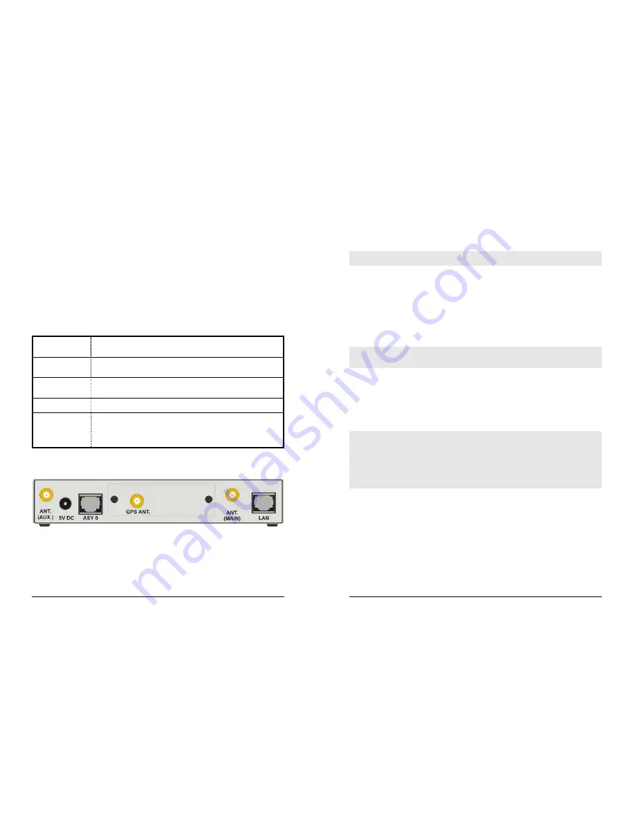
Only one of the above options can be fitted and will occupy the area of the rear panel
normally covered with the blanking plate. For example, if the GPS option is fitted, the rear
panel will appear as shown below:
WR41 Series Installation Guide
9
2 Installation
Note: You will not be able to use the router for remote communication until you have
subscribed to a suitable wireless network service.
WR41 series products are designed for indoor use (office or home). They should be
positioned on a smooth, level surface making sure that there is adequate ventilation. Do
not expose them to extremes of heat or cold, strong magnetic fields or liquids.
It is important to remember that these products are wireless devices just like a mobile
phone, so they will only operate reliably if there is a good quality signal from the network.
For many applications the stub antenna provided will be suitable but in some
circumstances it may be necessary to use a window-mounted or magnetically mounted
antenna with an extended cable to allow the antenna itself to be positioned to provide the
best possible signal reception. Digi International can supply a range of suitable antennas.
Important: If you are going to be using the Sar/OS Connection Wizard to configure the
unit’s Ethernet port and also connect it to your GSM/3G network, skip this section and
proceed to Configuration.
Step 1 - Installing the SIM card(s)
The router incorporates two separate SIM card holders so that if your application
demands it, you may install SIMs for two different networks. This means that one wireless
service may be used as a back-up service in the event that the primary service fails in
some way. By default, SIM 1 is the default SIM used for access to the primary network
and SIM 2 is used for the back-up network.
Notes:
1. SIM 1 and SIM 2 can NOT be used to access two networks simultaneously.
2. When using the WR41-C, not all networks require/support the use of Removable User
Identity Modules (R-UIM’s). If your service provider does not support R-UIMS, your router
may have been “provisioned” for use on your chosen network before you receive it and
this stage of the installation procedure will not be required. If your router has NOT been
provisioned, you will need to contact your service provider to obtain an “IMSI” and “NAI” in
order to provision the unit manually.
The SIM card(s) should be inserted into SIM cardholders on the right of the front panel as
illustrated below.


