background image

© 2012 JSB TECH Pte Ltd. All rights reserved.


CHAPTER 6: WARRANTY 

Digi-Pas

®


2-Axis High Precision Digital level is warranted to the original purchaser to be free from defects in

workmanship  and  material.  JSB  Tech  will,  at  its  option,  repair  or  replace  any  defective  part  which  may 
malfunction  under  normal  and  proper  use  within  a  period  of  2  (two)  years  from  the  date  of  purchase.  The 
forgoing warranty shall not apply to defects resulting from misuse, abuse, assignment, or transfer by the Buyer. 
Buyer-supplied  software  or  interfacing,  unauthorized  modification  or  operation  outside  of  environment 
specifications  for  the  product.  JSB  Tech  does  not  warrant  that  the  operation  of  instrument  software,  or 
firmware, will be uninterrupted or error free. The exclusive remedy under any and all warrants and guarantees, 
expressed herein, and we shall not be liable for damages from loss or delay of  equipment uses, consequential, 
or incidental damage. No other Warranty is expressed or implied. JSB Tech specifically disclaims the implied 
warranties of merchantability and fitness for a particular purpose. 

Manufactured by: 

JSB TECH PTE LTD 

Email:[email protected] 

www.digipas.com 

JIM-2-02001-99 

Distributed by: 

Summary of Contents for DWL2000XY

Page 1: ...ovation Technology Driven USER MANUAL 2 Axis Precision Digital Level Model DWL2000XY REVISION 1 00 Note Contents in this instruction manual is continuously updated please check Digi Pas website for la...

Page 2: ...We are constantly at work searching out a variety of high quality high performance tools to offer at the best prices possible Our commitment to you is that we will not offer cheap junk anywhere on our...

Page 3: ...tion which is protected by copyrights All rights are reserved No part of this manual may be photocopied reproduced redistributed or translated to another language without prior written consent of JSB...

Page 4: ...TER 2 SETTING UP Operating Procedure Mounting Device on Fixture CHAPTER 3 USER INTERFACE Single Axis Mode Interface Dual Axis Mode Interface Main Menu Icon Functions CHAPTER 4 FEATURES AND SETTING Abs...

Page 5: ...0 Cable 5 metre PC SYNC Software Professional Edition Optional Operating Temperature 10 C to 50 C Calibrated 14 F to 122 F Calibrated Dimension mm 188 x 62 x 37 Nett Weight Approx 580 gram User Self...

Page 6: ...croll right MODE Change the function and display mode Selection the function UNIT Change the unit degree mm M In FT of the measurement Scroll left Buzzer sound alert LCD Colour graphic digital display...

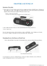
Page 7: ...e 3 Device ready to use Note For maximum accuracy perform calibration refer to APPENDIX User Calibration or Absolute Level refer to Chapter 4 Absolute Level for more details before measurement Mountin...

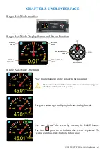
Page 8: ...asured Please ensure the contact surfaces of the device and measuring plane are clean and free from dust particles The green arrow sign on display indicates the higher side User may freeze the screen...

Page 9: ...d measuring plane are clean and free from dust particles The Target Ball or Bull Eye move towards the measured position similar to traditional Bubble vials The green arrow sign on display indicates th...

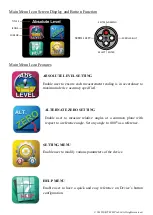
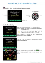
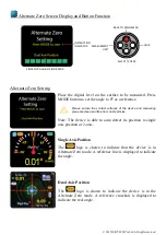
Page 10: ...mum device accuracy specified ALTERNATE ZERO SETTING Enable user to measure relative angles at a common plane with respect to a reference angle Set any angle to 0 00 as a reference SETTING MENU Enable...

Page 11: ...full Please ensure the contact surfaces of the device and measuring plane are clean and free from dust particles Note The device is able to auto detect its position is single axis position or dual axi...

Page 12: ...ee from dust particles Note The device is able to auto detect its position is single axis position or 2 axis Single Axis Position The logo is shown to indicate that the device is in Alternate Zero mod...

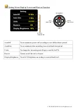
Page 13: ...ding to user defined time period AutoDim To set automatic dim according to user defined time period Units To change the measuring unit Degree mm M In FT Buzzer To turn on off the device buzzer Display...

Page 14: ...C or 4 F to 140 F When the device is not in used the batteries are to be removed from the device Cleaning 1 Keep the device dry and clean Remove any moisture or dirt with a soft dry cloth before meas...

Page 15: ...supplied software or interfacing unauthorized modification or operation outside of environment specifications for the product JSB Tech does not warrant that the operation of instrument software or fi...

Page 16: ...80 to Position 2 Press the MODE button again to start the calibration at Position 2 and wait until the countdown reach 0 the LCD screen displays Calibration 3 3 Place the device 90 on the side of Mast...

Page 17: ...vice during each count down period Press the MODE button again to start the calibration and wait until the countdown reach 0 the LCD screen displays Calibration 6 6 Turn the device 180 and place on th...

Reviews: