Diamond OASI 8M BM/LUX Manual Download Page 16

I

UK

D

E

F

NL

P

S

DK

FIN

B

GR

CZ

EE

LV

LT

H

M

PL

SK

SLO

I

UK

D

48

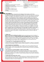
1. PULIZIA DELLA VASCA BAGNOMARIA
1
2

2. SOSTITUZIONE DELLE LAMPADE
Attenzione:

1

2.

3

4

LAMPADE AD INFRAROSSI 5

6

7.

8

9

10.

LAMPADE D’ILLUMINAZIONE AD INCANDESCENZA 11.

12

. Togliere l’alimentazione elettrica, agendo sull’interruttore generale e sfilando la spina dalla presa.
.

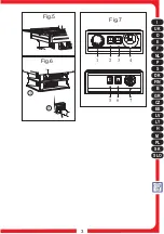
Prima di effettuare una qualsiasi operazione sulle lampade attendere che tutti i componenti si

siano raffreddati. . Aprire la cupola normalmente.

Togliere l’alimentazione come descritto nel Capitolo

1. . Svitare le viti sul lato del coperchio. . Sollevare il coperchio della plafoniera per aver accesso ai
gruppi lampade.

. Svitare, dall’esterno, le viti di fissaggio del corpo

lampada. . Svitare le viti di fissaggio della parabola, asportandola.

Togliere le pipe alle estremità della

lampada. . Svitare i bulloncini che fissano i contatti elettrici alle due estremità della lampada ad infrarossi.

. Sfilare la lampada ad infrarossi dalla sua sede e sostituirla con una originale Tecfrigo.

Ripristinare il

tutto procedendo in senso inverso.

Svitare la

lampada ad incandescenza e sostituirla con una nuova.

. Ripristinare il tutto procedendo in senso

inverso

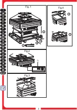
Aprire il rubinetto posto su un lato della macchina. . Pulire le pareti della vasca con spugna morbida

inumidita con acqua o detergenti neutri. . Asciugare tutto con cura usando un panno morbido e pulito.

. Chiudere il rubinetto della vasca e ripristinare l’alimentazione elettrica
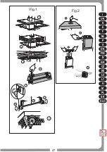
(Vedi Fig. 1).

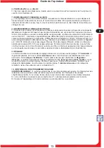
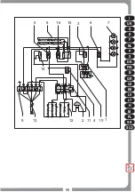
. Togliere l'alimentazione elettrica. . Scollegare il motoriduttore dall'alimentatore. . Togliere le viti di

fissaggio del vassoio superiore e rimuoverlo assieme alla cupola. . Liberare la staffa di sollevamento e
abbassare la parte mobile della guida. . Sfilare verso l'alto il motoriduttore. . Posizionare e bloccare le
piastrine di fissaggio sul nuovo motoriduttore. . Rimontare il tutto procedendo in senso inverso(Fig.2)

3

4

5

3. SOSTITUZIONE DEL MOTORE DI SOLLEVAMENTO DELLA CUPOLA
1

2

3

4

5

6

7

1. CLEANING THE BAIN-MARIE BASIN
1

2

3.

4

5

2. REPLACEMENT OF THE LAMPS
Warning:
1

2

3

4.

INFRARED LAMPS

5

6

7.

8

9

10

INCANDESCENT LAMPS 11

12.

3. REPLACEMENT OF THE COVER'S LIFTING MOTOR
1.

2

3

4.

5

6.

7

. Turn off the power switch and pull the plug out of its socket. . Open the tap on one of the machine's

sides.

Clean the basin walls with a sponge dipped in water or neutral detergents. . Carefully dry each

item with a dry, clean cloth. . Turn the tap off and reconnect the appliance to the power supply.

before attempting to carry out any operation on the lamps, wait for all components to cool down.

. Open the cover. . Turn the appliance off, as described in Chapter 1. . Loosen the screws on the side

of the cover.

Lift the cover of the ceiling lamp to gain access to the lamp units.

. From the outside, loosen the screws fastening the lamp unit. . Loosen the screws holding the parabola

in place and remove it.

Remove the attachment plugs at the ends of the lamp.

. Loosen the bolts that

fix the electrical contacts to the two ends of the infrared lamp.

. Remove the infrared lamp from its seat

and replace it with a new original Tecfrigo one.

. Refit all parts by following the above instructions in

reverse order.

. Unscrew the incandescent lamp and replace it with a new

one.

Refit all parts by following the above instructions in reverse order (see fig. 1).

Turn the appliance off. . Disconnect the gear motor from the power supply unit. . Remove the screws

fastening the top tray in place and remove the tray along with the protective cover.

Release the lifting

bracket and lower the mobile part of the guide. . Pull the gear motor out.

Position and fasten the fixing

plaques onto the new gear motor. . Refit all parts by following the above instructions in reverse order
(see fig. 2).

1. REINIGUNG DER WASSERBADWANNE
1.

2

3.

4.

5

2. AUSTAUSCH DER LAMPEN
Achtung:

1

2

3.

4

INFRAROTLAMPE 5

6.

7.

8.

9.

10.

BELEUCHTUNGSGLÜHLAMPEN 11

12

3. AUSTAUSCH DES HUBMOTORS DER KUPPEL
1.

2.

. 3

4

5.

6.

7.

Schalten Sie den Strom ab, indem Sie den Hauptschalter betätigen und den Stecker aus der Steckdose

ziehen. . Öffnen Sie den Hahn, der sich auf einer Seite der Maschine befindet.

Reinigen Sie die

Wannenwände mit einem weichen, mit Wasser befeuchteten Schwamm und neutralen Reinigungsmitteln.

Trocknen Sie alles sorgfältig mit einem weichen und sauberen Tuch ab. . Schließen Sie den

Wannenhahn und stellen Sie die Stromversorgung wieder her.

Bevor sie irgendeinen Eingriff an den Lampen vornehmen, warten Sie, bis alle Bestandteile

abgekühlt sind. . Die Kuppel auf normale Weise öffnen. . Strom wie im Kapitel 1 beschrieben
abschalten.

Die Schrauben auf der Deckelseite lösen. . Den Deckel der Deckenleuchte anheben, um

zu den Lampengruppen Zugang zu erhalten.

. Lösen Sie von außen die

Befestigungsschrauben des Lampenkörpers.

Lösen Sie die Befestigungsschrauben der Parabel und

nehmen Sie sie heraus.

Entfernen Sie die Stecker an den Lampenenden.

Losen Sie die

Schräubchen, mit denen die elektrischen Kontakte an den beiden Extremitäten der Infrarotlampe befestigt
sind.

Ziehen Sie die Infrarotlampe aus ihrem Sitz und ersetzen Sie sie durch eine Tecfrigo-

Originallampe.

Alles in umgekehrter Reihenfolge wieder zusammensetzen.

. Schrauben Sie die Glühlampe heraus und ersetzen Sie sie durch

eine neue.

. Alles in umgekehrter Reihenfolge wieder zusammensetzen (siehe Abb. 1).

Strom wie abschalten.

Den Motorinduktor von der Speiseleitung trennen

. Lösen Sie die

Befestigungsschrauben des oberen Tabletts und entfernen Sie es zusammen mit der Kuppel. . Befreien
Sie die Stützbügel und senken Sie den beweglichen Teil der Führung ab.

Ziehen Sie den Motorinduktor

nach oben heraus.

Positionieren Sie die Befestigungsbleche auf dem neuen Motorinduktor.

Alles in

umgekehrter Reihenfolge wieder einsetzen. (Siehe Abbildung 2).

Summary of Contents for OASI 8M BM/LUX

Page 1: ...The catering program Production code OASI 8M BM LUX Mod OASI 8M BM LUX 08 2005 ...

Page 2: ...I UK D E F NL P S DK FIN B GR CZ EE LV LT H M PL SK SLO 2 Fig 1 Fig 4 Fig 2 Fig 3 5 3 2 2 4 3 A II 0 I A B B ...

Page 3: ...I UK D E F NL P S DK FIN B GR CZ EE LV LT H M PL SK SLO 3 7 5 6 II 0 I 0 I 0 I 1 2 3 4 Fig 7 Fig 5 Fig 6 5 A 1 ...

Page 4: ... at the same temperature until defrosting is completed if this is not carried out the compressor will continue to operate leading to a wasteful consumption of electricity and poor performance If the appliance is not working and unused it is indispensable to keep the door open at least 10 cm 1 UNPACKING INSTRUCTIONS CARDBOARD BOXES 1a WOODEN CRATES 1b 2 3 4 5 6 7 8 2 OPENING THE PROTECTIVE COVER 1 ...

Page 5: ... H07 VVF for external settings Insert the plug in the socket The machine is not supplied with a plug Provide the power supply cable with a plug fulfilling the power requirements indicated on the rating plate do not use three way adapters and reduction adapters see fig 6 The appliance features controls situated in a protected panel to adjust the temperature in the appliance to switch on the resisto...

Page 6: ...aran dass die ausgestellten Produkte nicht über die Ablagen oder Gitter hinnausstrecken dürfen Sollte es durch die Luftfeuchtigkeit oder die zu kühlenden Produkte zu außergewöhnlicher Bildung von Eis auf dem Verdampfer kommen empfehlen wir den Kompressor auszuschalten und die Ware während des Abtauens bei gleicher Temperatur in dem vorgesehenen Behälter aufzubewahren andernfalls arbeitet der Kompr...

Page 7: ...n übereinstimmen Überprüfen Sie dass die Steckdose Versichern Sie sich dass am Aufstellungsort keine Explosionsgefahr besteht AD Das am Gerät angebrachte Speisekabel ist H05 VVF für Innenräume geeignet Für andere Aufstellungsorte muss das Kabel durch ein geeignetes ersetzt werden z B mit dem Kabel HO7 VVF für Außenbereiche Stecker in die Steckdose stecken Die Maschine ist nicht mit einem Stecker a...

Page 8: ...ERTURA DE LA CAMPANA DE PROTECCIÓN 1 2 A 3 LIMPIEZA DE LA CUBA INTERIOR 1 2 3 A B 4 4 LIMPIEZA DE LA CAMPANA Y DEL EXTERIOR 1 2 3 4 5 DISTANCIADORES DE SOPORTE DE LAS CUBETAS 1 2 3 Si se verificase una producción anómala de hielo en el evaporador causado bien por la humedad del aire o de los productos que se quieren refrigerar les aconsejamos que paren el compresor y que saquen y coloquen los alim...

Page 9: ... ambientes externos Introducir el enchufe La máquina se suministra sin enchufe Dotar el cable de un enchufe conforme a la norma adecuado a la carga indicada en la placa de datos no utilizar ni clavijas triples ni reducciones Véase figura 6 El equipo tiene mandos de regulación situados en el cuadrante protegido Regula la temperatura del equipo Sirve para accionar las resistencias de la cuba de baño...

Page 10: ...ition afin d en faciliter l élimination Il est possible de bloquer l appareil en agissant sur les roues avec frein voir illustration 1 Brancher la fiche au réseau électrique selon les indications du Chapitre 8 Appuyer sur l interrupteur de l élévateur électrique en position II jusqu à l ouverture complète en fin de course voir illustration 2 Enlever la pellicule de protection de l acier inox Netto...

Page 11: ... sur l appareil S assurer que la prise d alimentation est S assurer qu il n y a aucun danger d explosion AD dans le local S assurer que le câble d alimentation monté sur l appareil est H05 VVF câble prévu pour des usages internes Pour des usages différents utiliser un câble plus adapté par exemple H07 VVF pour usages externes Introduire la fiche dans la prise Aucune fiche n est fournie avec la mac...

Page 12: ...EN VAN DE INTERNE BAK 1 2 3 A B 4 4 HET REINIGEN VAN DE KOEPEL EN VAN DE BUITENKANT 1 2 3 4 5 DRAGERS VAN DE BAKKEN 1 2 3 Bij abnormale ijsvorming op de verdamper die wordt veroorzaakt door de luchtvochtigheid of door de te koelen producten is het raadzaam de compressor uit te schakelen en de waren in een geschikte op dezelfde temperatuur gekoelde houder te plaatsen voor de tijd die nodig is voor ...

Page 13: ...ische eigenschappen heeft Controleer of er in de ruimte van installatie geen gevaar voor explosie bestaat AD De voedingskabel die op het toestel aangesloten is is H05 VVF geschikt voor gebruik binnenshuis Voor andere installatieplaatsen dient de kabel met een daarvoor geschikt type te worden vervangen bijvoorbeeld H07 VVF voor buitengebruik Steek de stekker in het stopcontact De machine wordt zond...

Page 14: ...Εγχειρίδιο συντηρητή Pokyny pro údržbu Hooldusjuhend Instrukcija tehniskās apkopes darbiniekam Techninio aptarnavimo darbuotojo vadovas Karbantartási kézikönyv Manwal għall manutenzjoni Podrecznik obslugi konserwacyjnej Príručka pre údržbára Priročnik za vzdrževalno osebje Wartungshandbuch Maintenance manual Manual de mantenimiento I UK D E F NL P S DK FIN B GR CZ EE LV LT H M PL SK SLO I UK D E F...

Page 15: ...I UK D E F NL P S DK FIN B GR CZ EE LV LT H M PL SK SLO 47 Fig 1 3 4 5 6 11 7 8 8 9 Fig 2 4 5 3 6 ...

Page 16: ... loosen the screws fastening the lamp unit Loosen the screws holding the parabola in place and remove it Remove the attachment plugs at the ends of the lamp Loosen the bolts that fix the electrical contacts to the two ends of the infrared lamp Remove the infrared lamp from its seat and replace it with a new original Tecfrigo one Refit all parts by following the above instructions in reverse order ...

Page 17: ...fonnier pour accéder aux groupes de lampes Dévisser de l extérieur les vis de fixation du corps de la lampe Dévisser les vis de fixation de la parabole et la retirer Enlever les prises à pipe aux extrémités de la lampe Dévisser les petits boulons fixant les contacts électriques aux deux extrémités de la lampe à infrarouges Extraire la lampe à infrarouges de son logement et la remplacer par une nou...

Page 18: ...I UK D E F NL P S DK FIN B GR CZ EE LV LT H M PL SK SLO 55 t 10 4 1 11 14 12 2 6 13 9 7 8 15 16 3 5 M 24Vcc ...

Page 19: ...a Flotador Interruptor Interruptor Lámparas Lámparas IR Caja de bornes Motorreductor Relè Resistencia Enchufe Termostato Regulador lámparas IR Interruptor 1 2 3 4 5 6 7 8 9 10 11 12 13 14 15 16 Alimentateur Vibreur sonore alarme niveau Commande vitrine bombée Flotteur Interrupteur Interrupteur Lampes Lampes IR Bornier Motoréducteur Relais Résistance Prise de courant Thermostat Régulateur d énergie...

Reviews: