DA435HA: 99901219:
2-2
WARNING
THE INSTALLER OF THE DRIVELINE MUST INSPECT
THE FINAL POSITION OF THE DRIVELINE TO
DETERMINE WHETHER ITS LOCATION PROVIDES
SUFFICIENT PROTECTION TO AN OPERATOR, OR
OTHER PERSONNEL, FROM HAZARDS ASSOCIATED
WITH A ROTATING DRIVELINE. IF PROTECTION IS
INSUFFICIENT, THE INSTALLATION OF A GUARD IS
REQUIRED. IF YOU ARE UNSURE OF METHODS TO
GUARD A ROTATING DRIVELINE, CALL IOWA MOLD
TOOLING CO., INC. FOR INSTRUCTIONS. FAILURE
TO DO SO MAY RESULT IN SERIOUS INJURY OR
DEATH.
19980930
2-2-2. DRIVELINE AND PUMP
INSTALLATION
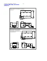
The pump may be driven as shown in Figure B-2 as
an optional method to the one shown in Figure B-1.
The following steps are a guide in this application.
NOTE
BEFORE INSTALLING DRIVELINE, REFER TO
PARAGRAPH 2-4 FOR PROPER DRIVELINE
INSTALLATION TECHNIQUES.
1. Install the PTO (refer to Paragraph 2-2-1).
2. Loosely bolt the pump mounting bracket (A) to
the adjustable bracket (B) in Figure B-2.
3. Bolt the adjustable bracket to the frame at a
point that will not exceed 48" (122cm) from the
PTO and will not cause a joint angle greater than 3°.
4. Check the pump rotation and install pump, pump
end yoke and PTO end yoke.
5. Size, cut and weld the driveline to the necessary
length. Ensure driveline balance and run out meet
specification. Allow 1" (2.54cm) extra for PTO end
yoke.
6. Install driveline in phase with proper operating
angle calculations, lock set screws and grease U-
joints and mating spline.
7. Ensure all mounting bolts are tight.
2-3. COMPRESSOR INSTALLATION
See Installation Kit Drawing in the Parts Section for
specific installation and parts information.
FIGURE B-2. DRIVELINE & PUMP INSTALLATION


