Diamond Systems JMM-5000-AH User Manual Download Page 9


JMM-5000 User Manual Rev B.01 

www.diamondsystems.com


Page 9


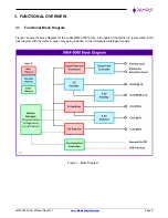
4.  POWER SUPPLY OPERATION 

4.1 

Source Selection 

The  power  supply  takes  its  input  from  either  the  main  input  connector  or  the  optional  backup  /  battery  input 
connector, with precedence given to the main input connector. If the input voltage on the main input connector is 
above the designated threshold voltage, it will be used as the source for the power supply. If the input voltage falls 
below the minimum, the supply will automatically switch to the backup / battery input. If this secondary input does 
not have sufficient voltage, the supply will shut off. 

The design supports the use of either single or dual power sources using the LTC4417 chip. 


4.2 

+5V Output Functionality 

The +5V output uses a multi-phase design.  The 5V is generated from a dual LTC3890 switch. Each switch output 
can produce up to 5A of output current for a total of 20A capacity with all 4 outputs enabled. In this fashion the 
output  efficiency  can  be  optimized  based  on  the  load,  resulting  in  higher  efficiency  across  the  full  rated  output 
power of the supply.  


4.3 

+12V Output Functionality 

The  LT3790 synchronous 4-switch buck-boost  voltage/ current regulator  controller  is  used for  generating  +12V 
output. The current output is limited to 8A maximum. 


4.4 

+3.3V Output Functionality 

A  TI-based  power  module  is  used  for  generating  +3.3V  output  at  5A  maximum.  The  LMZ31710  is  a  SIMPLE 
SWITCHER power module and an easy-to-use integrated power solution that combines a 10A DC/DC converter 
with power MOSFETs, a shielded inductor, and passives in a low profile, QFN package. The module is powered 
using the 5V supply. 


4.5 

+5V Standby Output Functionality 

A LT8620 2A regulator is used for the +5V standby supply. The +5V standby supply is used to supply the power 
controller  and  to  generate  the  +3.3V  standby  voltage.  +5V  standby  at  1A  maximum  is  available  at  the  output 
connector. 


4.6 

+3.3V Standby Output Functionality 

The AP7167-SPG-13 is used for generating the +3.3V standby supply. The +3.3V standby supply is used to supply 
the PIC microcontroller and the USB to I2C chip. 3.3V standby 0.1A maximum is available at the output connector. 


4.7 

Input Protection 

JMM-5000  includes  an  input  protection  circuit  based  on  the  LTC4364  chip.  This  device  provides  surge  /  spike 
protection,  load  dump  protection,  overvoltage  /  under  voltage  protection,  reverse  polarity  protection,  and  input 
current limiting (circuit breaker). Filtering is also added to limit noise reflected back onto the input. 


Summary of Contents for JMM-5000-AH

Page 1: ...ion B 01 Copyright 2016 2022 FOR TECHNICAL SUPPORT Diamond Systems Corporation PLEASE CONTACT 158 Commercial Street Sunnyvale CA 94086 USA support diamondsystems com Tel 1 650 810 2500 www diamondsyst...

Page 2: ...put Functionality 9 4 5 5V Standby Output Functionality 9 4 6 3 3V Standby Output Functionality 9 4 7 Input Protection 9 4 8 Remote On Off 10 4 9 Advanced System Controller 10 5 Connector Location and...

Page 3: ...er supply problems described below To avoid this type of failure only perform assembly operations when the system is powered off Sometimes boards are stored in racks with slots that grip the edge of t...

Page 4: ...ad VIN 12V TA 25 C Extremely low ripple 12mV peak to peak ripple at 5V output 0 20A load VIN 12V TA 25 C High efficiency 92 94 at 5V output 0 20A load VIN 12V TA 25 C Excellent transient load response...

Page 5: ...with power dissipation of 100W or less The height of the heat sink conforms to PC 104 height limits of 0 435 11mm max height above the PCB top surface The heat sink configuration may have a lower tota...

Page 6: ...L OVERVIEW 3 1 Functional Block Diagram Figure 1 shows the block diagram for the Jupiter MM 5000 family All models of the family are represented in the lock diagram with the items in green only being...

Page 7: ...com Page 7 3 2 Mechanical Board Drawing Figure 2 shows the mechanical drawing for Jupiter MM 5000 with locations of the key features Figure 3 is a dimensioned drawing of the Jupiter MM 5000 The power...

Page 8: ...JMM 5000 User Manual Rev B 01 www diamondsystems com Page 8 Figure 3 Dimensioned Mechanical Drawing...

Page 9: ...witch buck boost voltage current regulator controller is used for generating 12V output The current output is limited to 8A maximum 4 4 3 3V Output Functionality A TI based power module is used for ge...

Page 10: ...nd in the Janus MM 5000 Software Users Manual 4 9 Advanced System Controller The intelligent Jupiter 5000 models include a system controller that offers advanced configuration control and monitoring f...

Page 11: ...4 16 bit extension connector J3 PCI Bus connector PCI 104 J4 Not present J5 Factory use microcontroller programming J6 Not present J7 Primary input power connector J8 Secondary input power connector J...

Page 12: ...erminals J7 Vin 7 34VDC 1 Vin 7 34VDC 2 GND 3 GND 4 Connector Part Number 1827884 Mating Part Number 1827729 6 2 Secondary Power Input Connector J8 Power can also be provided from a battery source thr...

Page 13: ...1 5V out 2 12V out 2 5V out 3 3 3V out 3 GND 4 GND 4 GND 5 GND 5 GND 6 5V standby 7 Connector J9 Part Number 1827910 Mating part Number 1827758 Connector J10 Part Number 1827897 Mating part Number 64...

Page 14: ...bit bus connector J1 PC 104 16 bit bus connector A1 B1 Ground A2 B2 A3 B3 5V A4 B4 A5 B5 5V A6 B6 A7 B7 12V A8 B8 Ground D0 C0 Ground A9 B9 12V D1 C1 A10 B10 D2 C2 A11 B11 D3 C3 A12 B12 D4 C4 A13 B13...

Page 15: ...AD12 8 3 3V C BE1 AD15 3 3V 9 SERR GND SB0 PAR 10 GND PERR 3 3V SDONE 11 STOP 3 3V LOCK GND 12 3 3V TRDY GND DEVSEL 13 FRAME GND IRDY 3 3V 14 GND AD16 3 3V C BE2 15 AD18 3 3V AD17 GND 16 AD21 AD20 GND...

Page 16: ...d through a transient voltage suppressor TVS on the board The TVS is rated for 1 500 watt surges However it could be damaged by sustained voltages above 35V 3 Once the input voltage is in the valid ra...

Page 17: ...ts jupiter5000 The graphical user interface GUI program provides a control panel that provides access to all the features of the power supply An example screenshot is shown below The GUI is typically...

Page 18: ...maximum 12mV peak to peak at 5V output 0 20A load VIN 12V TA 25 C Efficiency 92 94 at 5V output 0 20A load VIN 12V TA 25 C Transient load response 72mV at 5V output 25 75 load step 2 5A usec ramp rat...

Reviews: