


JMM-5000 User Manual Rev B.01
Page 18
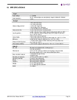
10. SPECIFICATIONS
Input
Input voltage
7
– 34VDC
Input protection
Over / under voltage, reverse polarity, surges, transients, reflected
noise
Output
Output voltage/current
+5V at 20A maximum
+12V at 8A maximum
+3.3V at 5A maximum
+5V standby at 1A maximum
+3.3V standby at 0.1A maximum
Output protection
Current limit and short circuit protection
Load regulation
±0.8%, Vmin to Vmax, 0-100% load on all outputs, -40°C to +85°C
0.35% maximum output voltage droop at 5V output, 0-20A load,
V
IN
= 12V, T
A
= 25°C
Output ripple
44mV peak-to-peak maximum
12mV peak-to-peak at 5V output, 0-20A load, V
IN
= 12V, T
A
= 25°C
Efficiency
92-94% at 5V output, 0-20A load, V
IN
= 12V, T
A
= 25°C
Transient load response
+/-72mV at 5V output, 25-75% load step, 2.5A/usec ramp rate,
V
IN
= 24V, T
A
= 25°C
Temperature stability
+/-0.5% at 5V output, 10A load, V
IN
= 24V, T
A
= -40°C to 85°C
General
On / Off
Remote or programmable on/off logic input
Dimensions
PC/104 form factor:
3.55” x 3.775” (90mm x 96mm) not including screw terminals
Maximum height .435” (11mm) above PCB top surface
Bus connection options
16-bit stackthrough ISA bus
32-bit PCI bus
Operating temperature
-40°C to +85°C (-40°F to +185°F)
Operating humidity
5 to 95% non-condensing
Shock
MIL-STD-202G compatible
Vibration
MIL-STD-202G compatible
Weight
6.3oz (178.6g) heat sink
8.1oz (229.6g) heat spreader
RoHS
Compliant