


Altair User Manual Rev A.02
www.diamondsystems.com
Page
47
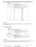
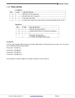
7.18 PWM CONTROL
Command:
Byte
Length
Value and Description
0
2
MESSAGE_SIG: Message signature
2
1
COMMAND_CONFIG_PWM:
Command ID
3
1
4: Indicating 4 bytes of data
4
4
4 bytes of data: channel number, 2 bytes of frequency, duty cycle percentage between 0 to 100
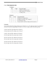
Response:
Byte
Length
Value and Description
0
2
MESSAGE_SIG: Message signature
2
1
COMMAND_RECEIVER_ACK: Command id for the message
3
1
1
4
1
Return status for the command
0: Operation completed successfully
1 or non-zero: Some problem in the operations
Comments:
This command enables PWM channels to generate PWM signals of certain frequency and duty cycle. The output
pins for different channels are as follows:
Channel #1: P1A/RC2 pin
Channel #2: P1B/RE6 pin
Channel #3: P1C/RE5 pin
Channel #4: P1D/REG4 pin
The response is a status message for successful completion of the command.