


Altair User Manual Rev A.02
www.diamondsystems.com
Page
28
5.
CONFIGURATION JUMPER DETAILS
This section explains the use of several jumper options on the Altair Baseboard.
The board contains jumper blocks for configuring the following features. The board also contains locations for
installation of 0-ohm resistors in place of all valid jumper positions for a rugged configuration. The 0-ohm resistors
are oriented and labeled in a way that provides easy understanding of their use and easy interpretation of their
settings.
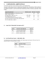
Jumper Group Function
Silkscreen Label
Reference Array Size
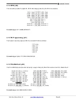
Serial Port 1 RS-422/485 mode differential termination
resistor; Enable or Disable
JP1
2 X 2
LCD panel supply voltage: 3.3V or 5V
LVDS VSEL
JP2
1 X 3
LCD backlight power: 5V or 12V
(+12V provided through the input power connector)
INV VSEL
JP4
1 X 3
LCD Panel Scan Direction; Normal Scan or Reverse Scan
JP5
2 X 2
LCD Panel Map; Map-A or Map-B
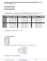
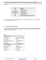
5.1 Serial Port 1 RS-422/485 Termination (JP1)
Setting
Termination Enable/Disable
Protocol
Open
Termination Disable (default)
RS-233
1
– 2
RS-422 Termination Enable
RS-422
3
– 4
RS-485 Termination Enable
RS-485
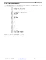
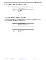
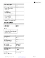
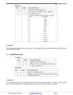
5.2 LCD Panel Power Select
– LVDS VSEL (JP2)
This jumper group must be configured according to input voltage required by the type of LCD panel that will be
attached to Altair’s LCD panel interface connector.
Setting
LCD Panel Voltage
1 - 2
+5V
2 - 3
+3.3V (default)