diamond mowers Rear Swing Flail Operator'S Manual Download Page 22

REAR SWING FLAIL 

OPERATOR’S MANUAL

CONTINUED ON NEXT PAGE

BELTS AND PULLEYS


Reversing Cutting Shaft Rotation:


Install the front shield

(11)

 for reverse rotation, or remove it for 

forward rotation.


Install the baffle with bolts

(12)  

for forward rotation, or remove it for 

reverse rotation.


Reference the parts pages for additional information.
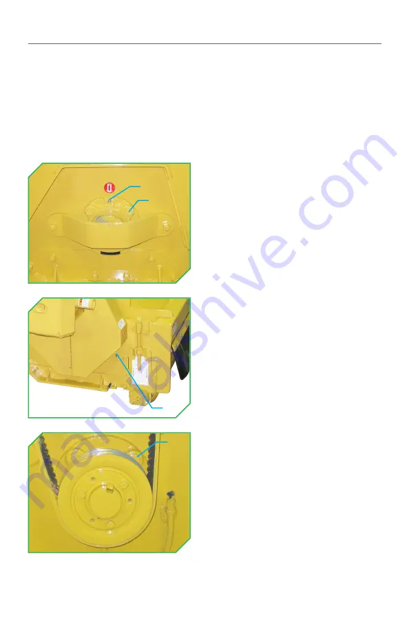
CUTTING SHAFT


Grease the cutting shaft bearing 
zerks

(1)

 (1 on each side of the flail) 

every 10 hours or daily with #2 
lithium based grease from a hand 
grease gun until grease purges from 
the bearing seals.  


Torque the cutting shaft bearing 
bolts

(2)

 to 90ft-lbs (122Nm) on each 

side of the flail every 50 hours 
or weekly. 


NOTE:

 The access covers covering 

the pulleys and belt must be 
removed to gain access to the 
cutting shaft bearing bolts 
located underneath the bottom 
pulley of the flail.

(1)

(2)

(1)

(2)

22

Summary of Contents for Rear Swing Flail

Page 1: ...00 WWW DIAMONDMOWERS COM PARTS 888 960 0361 WARRANTY SERVICE 888 960 0364 OPERATOR S MANUAL 350 EAST 60TH ST N SIOUX FALLS SD 57104 800 658 5561 605 977 3300 WWW DIAMONDMOWERS COM PARTS 888 960 0361 W...

Page 2: ...ions found in this operator s manual could lead to serious injury Operators who choose to operate this equipment without following instructions or who choose to operate this equipment in a manner inco...

Page 3: ...ans being there when you need us CONTACT US Parts 888 960 0361 parts diamondmowers com Warranty Service 888 960 0364 warranty diamondmowers com Main Office 800 658 5561 605 977 3300 Website www diamon...

Page 4: ...ork fast TRANSFERRED OWNERSHIP If you have acquired this flail mower from a previous owner we encourage you to register your equipment online By registering your Diamond Mowers unit you ll stay inform...

Page 5: ...TABLE OF CONTENTS INTENDED USE 6 TAKE A LOOK AROUND 7 GETTING STARTED 9 OPERATING YOUR FLAIL MOWER 13 MAINTENANCE INTERVALS 19 TROUBLESHOOTING 36 PARTS BOOK 38 INDEX 50...

Page 6: ...of obstructions and bystanders Any use on non vegetative material or in an area that is not clear of persons and property is strictly prohibited Any use outside of the aforementioned application is co...

Page 7: ...DRIVE All of our heavy duty flails use a high strength belt with an automatic self tensioner no manual adjustment needed BEARINGS For ultimate long life and reliability our flail cutting shafts and g...

Page 8: ...amage in the event of a collision SWING ARM Our fully articulating swing arm allows you to mow steep inclines and ditches as well as other hard to reach areas standard side mounted flails cannot go SW...

Page 9: ...raft beam links 1 if present to their float position NOTE Your draft beam links 1 if present may not look exactly the same as this example Mount the hitch frame 3 to the tractor s 3 Point hitch draft...

Page 10: ...tractor s 3 Point hitch draft beams NOTE Your draft beam stabilizers 6 and or spacers 7 if present may not look exactly the same as this example CONNECTING THE PTO DRIVE Slide the slip clutch 1 onto...

Page 11: ...lide it onto the slip clutch s splined shaft 4 Push until the spring loaded locking pin 6 on the PTO drive shaft 5 locks into place in the groove on the slip clutch s splined shaft 4 Push in the sprin...

Page 12: ...attachment to the tractor s auxiliary hydraulic remotes Make sure the connections are done to match the recommended lever control functions as described in the Operation section of this manual Refere...

Page 13: ...your safety and for the safety of others working with you Always wear applicable personal protective equipment PPE when operating Block off work area from bystanders livestock etc Bystanders must keep...

Page 14: ...haft has come to a complete stop before exiting the cab Contact with the cutting shaft and knives while in motion will cause serious injury or death The cutting shaft spins at a very high speed and ca...

Page 15: ...e room for exhausted material to be dispersed If you hear the cutting shaft or engine slow down lift up the head and or slow your ground speed A second pass may be needed for heavy brush or grass Comp...

Page 16: ...ve straight into the material keeping the deck low and level with the ground roller resting on the ground Maintain speed of the cutting shaft and ground speed REAR SWING FLAIL OPERATOR S MANUAL CONTIN...

Page 17: ...he top and cut the tree in 12 305mm increments With the Flail Mower lifted slightly drive straight into the material Allow enough time for the tree section to fall away while cutting Use a smooth quic...

Page 18: ...the cutting shaft and bearings as a result of driving down pancaking on top of the material REAR SWING FLAIL OPERATOR S MANUAL OPERATING TECHNIQUES Dropping the mower straight down pancaking on heavy...

Page 19: ...ulleys Adjust Cutting Shaft Grease Inspect Discharge Flap Inspect Gear Box Inspect Oil Ground Roller Oil Hitch Frame 3 Point Inspect Hydraulic Fittings Inspect Knives Inspect PTO Slip Clutch Drive Sha...

Page 20: ...install the new belt 2 Replace the access cover Pulley Alignment Use a straight edge 5 to confirm the cutting shaft 3 and motor 4 pulleys are in the same plane as the idler pulley 1 If pulley misalign...

Page 21: ...r the idler position stop bolt will be exposed Re attach the main center bolt to lock it into position Replace the belt 2 as illustrated dashed outline and access cover Disconnect the PTO drive shaft...

Page 22: ...ditional information CUTTING SHAFT Grease the cutting shaft bearing zerks 1 1 on each side of the flail every 10 hours or daily with 2 lithium based grease from a hand grease gun until grease purges f...

Page 23: ...il level check plug 1 Oil should be level with the port The gear box oil should be replaced after the first 50 hours of operation and then every 500 hours or annually Remove the oil drain plug 2 Use a...

Page 24: ...locks 3 from each side of the flail and ground roller DO NOT reassemble the bearing block hardware from one side of the flail on the other Lift the flail head for access to the ground roller Remove th...

Page 25: ...ly tighten or loosen the castle nut whichever exposes the hole first until the hole is fully exposed Liftthe ground roller insert and pull down on the ground roller shaft to check for end play 4 No en...

Page 26: ...of the grooved surface where the insert will mate to 4 Place a dot of RTV silicone sealant 12 on the groove between each hole Place the O ring 13 into the groove on the end cap Place the end cap onto...

Page 27: ...of the block 3 opening to the flat of the bearing shaft 16 Mount the bearing blocks 3 to the roller brackets 17 of the flail Use loctite 262 with primer 7649 on the hardware Torque the hardware to 75f...

Page 28: ...adjustment nuts 21 Tighten the lock nuts 18 and retaining plate hardware Torque the hardware to 75ft lbs 102Nm HITCH FRAME 3 POINT Inspect hitch frame 4 components every 10 hours or daily 3 Point hit...

Page 29: ...y leaks are observed stop immediately to prevent damage to your machine Hoses for any abrasions or cuts Replace damaged or worn hoses Attach hose wrap around critical points where hoses are likely pin...

Page 30: ...the cutting shaft Inspect the knife mounting bolts 2 and nylock nuts 3 for damage every 10 hours or daily Replace damaged components as needed Tighten nylock nuts 3 snug against the cutting shaft bra...

Page 31: ...p When rebuilding slip clutches 1 follow the below listed procedure Disconnect and remove the PTO drive shaft from the slip clutch 1 Loosen the six nuts 2 evenly and on opposite sides until loose Remo...

Page 32: ...PTO drive shaft 4 off of the gear box 9 Pull apart the PTO drive shaft 4 and grease all zerks with 2 lithium based grease Push the PTO drive shaft 4 back together Depress the locking pin 8 and push t...

Page 33: ...50 hours or weekly Replace as needed Always test a PTO drive shaft connection by giving it a hard tug in an attempt to disengage it Do not use a PTO drive shaft that fails to stay locked to a splined...

Page 34: ...rs around the joints Inspect all cylinder anchor hardware for wear or damage and replace as needed Breakaway Spring Tension Standard spring 6 tension is set with the springs 6 at 9 228mm measured from...

Page 35: ...SWING FLAIL OPERATOR S MANUAL SWIVEL If looseness or play is detected in the swivel replace the nylatron bearings 1 and the internal greaseless bearing not visible in the interior of the swivel It is...

Page 36: ...e the tractor s operator manual for more information Hydraulic hoses fittings are damaged and or is leaking Tighten or replace hoses and or fittings Hydraulic hoses are not attached to the tractor s a...

Page 37: ...s for assistance Misaligned pulleys Correct pulley alignment Excessive wear on gear box Diassemble and repair gear box Contact Diamond Mowers for a replacement PROBLEMS POTENTIAL CAUSE SOLUTION Mower...

Page 38: ...PARTS BOOK REAR SWING FLAIL...

Page 39: ...9 21 18 17 23 26 12 15 1 24 15 1 25 1 25 32 21 22 29 30 10 9 16 27 26 27 11 16 26 25 1 14 13 1 7 7 7 13 13 5 7 5 5 5 13 31 9 20 4 8 8 4 35 28 2 6 6 3 6 3 6 9 14 33 2 REAR SWING FLAIL PARTS BOOK SWING...

Page 40: ...RB 90DEGX 1 2MP 2 21 2234 14 1 4 GREASE ZERK STRAIGHT 3 23 0004 15 1 4 X 90 DEG GREASE ZERK 4 23 0009 16 CLEVIS PIN 2 27 0004 17 UPPER 3 PT PIN 1 27 0009 18 LOWER 3 PT PIN 2 27 0028 19 SWINGARM PIN 4...

Page 41: ...11 2005 6 3 X 12 WELDED CYLINDER W 2 SLUG 1 14 0037 7 1 2 MALE QUICK COUPLER 2 21 2119 REF PARTS DESCRIPTION REQ PART 8 HOSE 1 4 X 148 1 2MORB 90DEGX 1 2MP 2 21 2329 9 1 4 GREASE ZERK 2 23 0004 10 CLE...

Page 42: ...K HOSE 1 21 0002 25 1 8 GREASE ZERK 2 23 0003 26 BONNET RIGHT SWING 1 25 0101 BONNET LEFT SWING 1 25 0108 REF PARTS DESCRIPTION REQ PART 27 GROUND ROLLER BLOCK 2 31 0563 28 LOCK PLATE 4 41 0003 29 ADJ...

Page 43: ...REAR SWING FLAIL PARTS BOOK DECAL IDENTIFICATION Swing Flail Head 43...

Page 44: ...MM X 2 0 HEX CAPSCREW 8 11 0627 21 12MM X 40MM X 1 75 HEX CAPSCREW 1 11 0672 22 1 2 X 2 NC CARRIAGE BOLT 4 11 0718 REF PARTS DESCRIPTION REQ PART 23 3 8 X 1 H S NC SKT HEAD 1 11 0752 24 1 2 X 1 3 4 NC...

Page 45: ...0189 6 BEARINGSET 2 29 0190 7 YOKE CAT 4 80DEGREES NOT SHOWN 1 29 0191 8 621 3905 100 ASM 1 29 0192 REF PARTS DESCRIPTION REQ PART 9 OUTER GUARD 1 29 0194 10 INNER GUARD 1 29 0195 11 TUBE 1 29 0197 1...

Page 46: ...2 CLEVIS ASSEMBLY 1 14 1160 3 BUTT TUBE ASSEMBLY 1 14 1141 4 GLAND 1 14 1155 5 PISTON 1 14 1150 6 LOCKNUT 1 14 1120 7 SLUG 1 14 1191 8 SEAL KIT 1 33 0038 9 SET SCREW 1 11 2007 REAR SWING FLAIL PARTS B...

Page 47: ...2 CLEVIS ASSEMBLY 1 14 1160 3 BUTT TUBE ASSEMBLY 1 14 1140 4 GLAND 1 14 1155 5 PISTON 1 14 1150 6 LOCKNUT 1 14 1120 7 SEAL KIT 1 33 0038 8 SLUG 1 14 1191 9 SET SCREW 1 11 2007 REAR SWING FLAIL PARTS B...

Page 48: ...Q R 6 30 1345 16 THRUST PLATE REAR 2 30 1347 REF PARTS DESCRIPTION REQ PART 17 THRUST PLATE 6 30 1348 18 NAME PLATE 1 30 1349 19 DOWEL PIN 24 30 1350 20 DRIVE SCREW 2 30 1351 21 STUD REAR 2 30 1352 22...

Page 49: ...OD X 1 26 ID 5 11 2074 1 CASTLE NUT 6 21 1136 1 1 8 NPT PLUG 7 24 0273 1 O RING 2 7 8 OD 8 33 0031 1 SEAL TCM 132713TC 9 41 1533 1 ASSY GROUND ROLLER SHAFT 10 44 0780 1 SERVICE KIT GROUND ROLLER NOT S...

Page 50: ...ded Use 6 K Knives 7 30 Hardware 30 M Machine Requirements 9 Maintenance Chart 19 Mounting the Attachment 9 O Operation Safety Tips 13 Stowed Position 14 Techniques Finished Mow 16 Grass Brush Cut 15...

Page 51: ...Direction 21 22 S Shock Absorber 8 Skid Shoes 33 Spring Tension 34 Support Stands 9 28 Swing Arm 8 8 Swivel 8 35 T Tractor Requirements See also Machine Requirements Transferred Ownership 4 Troublesho...

Page 52: ...15 1102 RSF MANUAL...

Reviews: