Diagraph LA/4700 User Manual Download Page 21

Step 4 - Mount and Adjust the Product Detector

Goal: 

Determine which mounting location is ideal, either on the baseplate, on the snorkel, or on the 

conveyor system.

Goal: 

Adjust the sensor to detect just the product, and ignore background objects, such as forklift 

trucks, personnel, or other objects that may pass in front of the sensor’s view.

••••  Sub-Step (a)  ••••          

Determine if a product detector mounting location on the baseplate 
or snorkel (wipe-on) will work for this application. Typically, the 
location on the baseplate or snorkel is ideal for mounting ease and 
mobility. This location works best if the products are approaching 
from the side of the sensor, in relation to the tamp pad. If this 
location cannot apply the label in the desired position due to 
timing, mount the sensor in an alternate location (such as the 
conveyor) using the supplied mounting bracket.

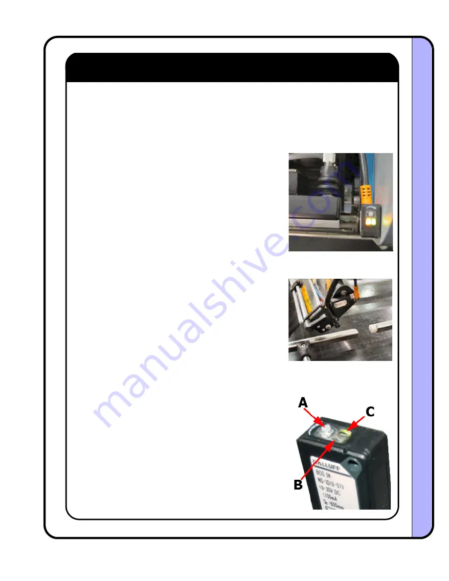
••••  Sub-Step (b)  ••••          

Adjust the sensor’s sensitivity to detect just the product, and ignore 
the background. This can be done by placing the actual product in 
the path of the sensor’s view. Adjust the sensitivity setscrew (A) 
until the yellow light (B) illuminates, and the green light (C) is 
steady and bright. The yellow light shows that the output is active. 
The green light shows the relative signal strength in the presence 
of the product. When the sensor is not detecting a product, the 
green light is on to show that the sensor is powered on. This can 
be useful for troubleshooting and calibration. Remove the product 
and verify that the yellow light is off. If not, adjust the setscrew 
counter-clockwise to reduce sensitivity. Once the background is 
eliminated from triggering the sensor, place the product under the 
sensor again to verify output.

Baseplate mount shown

Snorkel mount shown

Diagraph  - an ITW Company              LA/4700 User Manual - Revision B

Setup

Page 20

Setup

Summary of Contents for LA/4700

Page 1: ...4700 010 Revision B...

Page 2: ...n tinue specifications and designs shown in this manual without notice and without incurring obligation Diagraph has made every effort to verify the informa tion contained in this manual but reserves...

Page 3: ...00 UL 60950 using Diagraph an ITW Company approved items Units are only tested and qualified with Diagraph an ITW Company approved parts and accessories Use of other parts or accessories may introduc...

Page 4: ...ns In compliance with UL safety standards the stand must be secured to the surface where it is located Additionally this type of securing will result in greater product application accuracy 1 3 Docume...

Page 5: ...arrow Web 5 in Wide Web 9 in 0 5 in 12 7 mm Min to 4 0 in 101 6 mm Max 0 5 in 12 7 mm Min to 9 0 in 228 6 mm Max Product Rate LA 4700 800 PPM Max Temperature 41 F 104 F 5 C 40 C Humidity 10 to 85 RH N...

Page 6: ...mm Tamp Stroke 20 in cylinder 3 19 in 76 482 mm 3 in 76 mm 19 5 in 495 3 mm Air Consumption while running 2 5 CFM at 80 PSI 2 0 CFM at 80 PSI 5 CFM at 80 PSI Tamp Blow Distance Pad to product blow dis...

Page 7: ...d P N 4700 800W9L Wide Web WIPE Left Hand P N 4700 800W9R Wide Web WIPE Right Hand P N 4700 800T5L Narrow Web TAMP Left Hand P N 4700 800T5R Narrow Web TAMP Right Hand P N 4700 800T9L Wide Web TAMP Le...

Page 8: ...inch shaft P N 4700 630 9 inch shaft P N 4700 630W The nip assembly holds the label liner in constant contact with the drive roller It uses a non stick coating to avoid label build up This assembly i...

Page 9: ...is an optional device that allows the feed speed and label placement to be synchronized with changing linespeeds The Photocoder uses two photosensors that are spaced a fixed distance apart By measurin...

Page 10: ...holding torque The rewind is belt driven using an automatic tensioner This belt should be inspected for wear at the recommended service intervals The tamp pad captures the label from the drive module...

Page 11: ...operation of the tamp cylinder and the delivery of the label from the drive module to the product The manifold has two pressure regulators one for tamp pressure and the other controls both vacuum and...

Page 12: ...of the cylinder air assist or vacuum to change The Main Controller Assembly III is a third generation of Diagraph designed micro controller coupled with an interface board The Microcontroller Unit MCU...

Page 13: ...d durability elimination of any clutch or dancer arm and limit switch The control current set by the system in accordance to the state of operation directly controls the rewind s tension The system el...

Page 14: ...DC NPN type 6000 903 as shown 4600 903 is the older style with a flat lens The tamp pad sensors auto retract and label present and the label low sensor are diffuse light sensors All three sensors are...

Page 15: ...simplicity in design The sensor should not require adjustments since the threshold levels are set at the factory The sensor constantly monitors pressure and triggers an error on the system if the air...

Page 16: ...les and features which adds a great deal of diversity to the product line In this simplification the same MCU firmware and GUI memory run both the Printer Applicators PA 4600 PA 6000 and the Label App...

Page 17: ...e orientation for application The LA 4700 are capable of rotating and pitching about various axes to accommodate a wide range of label placement opportunities Select the best orientation from the give...

Page 18: ...odate a wide range of label placement opportunities Select the best orientation from the given measurements and desired label locations Top Down Side Apply Nose Down Nose Up Top Down TAMP FASA 50 in 1...

Page 19: ...edicated AC line drop is preferred This eliminates problems caused by other AC loads on the same line such as motors which create back EMF Disturbances such as these can cause erratic behavior system...

Page 20: ...Connect the clean dry compressed air line supplying 60 psi or greater at 2 5 CFM or better to the inlet air filter regulator of the system with the OSHA valve closed The air should be free of oil lubr...

Page 21: ...s the conveyor using the supplied mounting bracket Sub Step b Adjust the sensor s sensitivity to detect just the product and ignore the background This can be done by placing the actual product in the...

Page 22: ...ng OTS Screens on page 33 Power On Step 6 Enter Values for the System Settings Goal Enter System information pertaining to Application Mode Serial Baud Rate and Passcode Map Beginning in the Offline m...

Page 23: ...formation on how to make these selections Wipe or WASA System For a typical one wipe application the following settings provide a good start Tamp or FASA System For a typical one tamp application the...

Page 24: ...e correct pressure is set press down on the knob to lock it in position Remove the knob entirely by lifting it up past the unlock point if there is concern about system tampering TAMP FASA Step 9 Posi...

Page 25: ...m the liner to create a leader Route the liner around the dancer arm B and feed into the drive module Feed the liner under the gap sensor E and around the peel blade F Open the nip roller arm lever D...

Page 26: ...cer arm B and feed into the drive module Feed the liner through the gap sensor D and around the peel blade E Be sure to avoid webbing over the air assist tube F Open the nip roller arm lever C Take th...

Page 27: ...ose to the inner guide and slide the outer guide B to the edge of the liner and tighten the knurled screw Sub Step c 1 Loosen knob C and adjust the brush clamp across the label width to the mid positi...

Page 28: ...hat the label dispensed covers the ported vacuum holes and covers the label present sensor if equipped These screws adjust the tamp pad height in relation to the peel blade edge 2 Before locking the s...

Page 29: ...ed Conversely turning the setscrew counter clockwise increases the speed Sub Step c The air cushion absorbs the shock of the tamp returning to the fully retracted or home position To increase the amou...

Page 30: ...sure and counter clockwise to increase it Since the blow valve has an additional trim of a dedicated flow control set the pressure as high as necessary for vacuum Typically a pressure range between 30...

Page 31: ...to set the material for operation During the calibrate process the Status LED will flash green while calibrating 5 When calibration is complete the Status LED will either be green if the process was s...

Page 32: ...ng home but can impact the final return time of the tamp pad to the home position Increase the air cushion adjustment so that no metallic clank is heard when the cylinder retracts but not so much that...

Page 33: ...ll for the beginning 80 of the roll but equally as well for the remaining 20 If the vacuum is too high it will be most notable when the transfer to the product suffers It will also be noticeable over...

Page 34: ...e button below the text until it displays Yes The choices are left and right handed based on the direction of the drive module on the baseplate This is determined by facing in the direction of the fee...

Page 35: ...blank area of liner without interpreting this as a missing label GUI Version 1 29 and higher only The rewind profile changes the speed and tension to match the application requirement In five incremen...

Page 36: ...rate product delay distance 1 Blow 1 product trigger to 1 blow on a blow box application 2 Blows 1 product trigger to 2 blows on a blow box application 1 Wipe 1 product trigger to 1 label feed Wipe or...

Page 37: ...linespeed the more important the exact setting is entered ALL APPLY MODES PHOTO SPEED ENCODER ENABLED When the system is running with the Photo Speed Encoder enabled the product speed is automatically...

Page 38: ...ct surface before contact This allows the lightest touch of the label to the product which can accomplish nearly the same effect as a tamp blow on many products and have the benefit of positive contac...

Page 39: ...d far enough away from the system to allow for the label feeding to finish in time for application This works well for applications where each label is unique A final choice of Product Sensor 2 allows...

Page 40: ...active and a white background if no signal is present The Rewind Diagnostic screen will allow the user to test the motor by pressing the TEST button This will activate the motor briefly to verify oper...

Page 41: ...PA Unit Gap Sensor LA Unit LOW Label Low PD2 Product Detector 2 AUX Auxiliary Input CYL Cylinder Home PD1 Product Detector 1 The Pneumatics Diagnostic screen permits testing of the various valves on t...

Page 42: ...is offline due to error This includes Media Out Air Pressure Out Drive Errors Repeat Label or Tamp Threshold Exceeded etc Steady Warning Unit has experienced a condition that requires attention but it...

Page 43: ...input event Screen Functionality Input Event Description None No input event assigned Online Enter online mode Level activated Cannot enter online mode if there is an error Deactivate signal for offl...

Page 44: ...n B User Interface Page 43 User Interface 5 6 Information Screens Map Note Information screens can be entered while running online or offline The below columns indicate the menu structure for the give...

Page 45: ...itched 24 VDC supply are turned off Once off the screen will transition to the next following screen for turning it back on If this screen is entered but no selection is made within 10 seconds the scr...

Page 46: ...tion trigger but could not start timing sequence since the apply cycle was not complete On a FASA system this could mean that the second apply cycle has a product delay that is too short Label on Dete...

Page 47: ...m Errors Note Any of the following errors will place the unit in offline thus stopping operation Screen Screen Screen E02 Repeat Label Cycle E03 Repeat Tamp Cycle E04 Cylinder Not Home E06 Air Pressur...

Page 48: ...evision B Troubleshooting Page 47 Troubleshooting 6 3 Electrical Test Points Power Supply Terminals Measure these tests with a VOLT METER and the cables disconnected from the pc board Test Expected Re...

Page 49: ...tage If TP5 is correct replace board due to driver IC failure TP 2 Power Supply Ground 0 VDC TP 3 5 VDC Logic Supply 5 VDC 0 25 VDC Check TP5 for correct voltage If TP5 is correct replace board due to...

Page 50: ...T METER and the cables connected from the pc board Test Expected Result Coil A to Coil B Less than 2 Coil B to Coil C Less than 2 Coil C to Coil A Less than 2 Test Expected Result HALL A and Ground 0...

Page 51: ...roller is turning backwards liner is pulled from rewind Unit is incorrectly webbed Re web the label liner as seen on page 24 Unit is not correctly configured for left hand or right hand Confirm that...

Page 52: ...rter labels require a steeper angle to the product surface page 26 Wipe on brush position is too close to peel edge For labels longer than 2 inches 50 8 mm move the brush away from the peel blade edge...

Page 53: ...orted Open pad and check First column of holes should be open matching the width of the label Last column of holes matching the label s length should be open but only those matching the width of the l...

Page 54: ...See Tamp Cylinder Adjustments on page 27 Cylinder home sensor position too low Move the cylinder home sensor to a position where the cylinder is detected home later Air cushion set too slow The air cu...

Page 55: ...mentally simple as a roll of labels would appear there are a few key areas that can cause problems and these problems are sometimes falsely associated with the equipment and not the label The typical...

Page 56: ...ed Start the MTool2 program and once the system s param eters are read select the tab to download new firmware This takes approximately one minute and concludes by re reading the parameters Maintenanc...

Page 57: ...Supply 4700 505 Drive Module Power Capacitor 6146 617 YES Peel Blade Narrow Web 6146 617W YES Peel Blade Wide Web NIP ROLLER ASSEMBLIES Narrow and Wide Versions Contain Nip Roller Nip Roller Shaft Ni...

Page 58: ...mbly III MCA III Includes MCU Board Interface Board User Interface Enclosure 4600 503 Rewind BLDC Motor 4600 950 YES MAINTENANCE KIT Wear Items Set Includes 2 Rewind Belts 3 Spindles 2 ea Springs 3 Un...

Page 59: ...window 6000 903 new style sphere window YES Auto retract Label low or Label present sensor and PUR cable 1 sensor cable cover per kit 6000 420 Ethernet Module Wired and Wireless 4700 907 Photo Speed...

Page 60: ...Diagraph an ITW Company LA 4700 User Manual Revision B Maintenance Page 59 Maintenance 7 4 Assembly Views and Part Numbers...

Page 61: ...Diagraph an ITW Company LA 4700 User Manual Revision B Maintenance Page 60 Maintenance...

Page 62: ...Diagraph an ITW Company LA 4700 User Manual Revision B Maintenance Page 61 Maintenance...

Page 63: ...Diagraph an ITW Company LA 4700 User Manual Revision B Maintenance Page 62 Maintenance...

Page 64: ...mation 8 1 Product Detector J2 J3 DB9 Female PIN Pin Description Pins 1 2 N C Pin 3 Ground Pins 4 5 N C Pin 6 24 VDC Supply Pin 7 N C Pin 8 Product Detector Input Pin 9 N C 8 2 Auxiliary Port Pin Out...

Page 65: ...1 2 3 N C Pin 4 Red Ground Switched Pin 5 Yellow Ground Switched Pin 6 24 VDC Supply Pin 7 Green Ground Switched Pin 8 9 N C 8 4 Serial Communication Pin Out J1 DB25 Female PIN Pin Description Pin 1...

Page 66: ...sures Detected In troubleshooting an application it may be desirable to determine if the supplied compressed air has caused an intermittent error condition Once the system detects that the pressure is...

Page 67: ...3 23 EEC Standards Conducted Emissions EN55 011 Harmonics EN 61000 3 2 Flicker EN 61000 3 3 Radiated Emissions EN55 011 Electrostatic Discharge ESD EN 61000 4 2 Radiated Immunity EN 61000 4 3 Fast Tra...

Page 68: ...ing Label Warning Error Label Shape Normal Irregular Product Detector Trailing Leading SYSTEM Apply Mode 1 Tamp 1 Tamp Blow 1 Blow 1 Wipe 2 Tamps 2 Tamp Blows 2 Blows 2 Wipes Passcode __ __ __ __ Phot...

Page 69: ...__________________________ Output 2 ____________________________ Output 3 ____________________________ Output 4 ____________________________ Output 5 ____________________________ Output 6 ____________...

Reviews: