


21
3 I/O Control
The I/O mode is a common control method in industry.
The grippers will monitor the pin states of Input 1 and Input 2 (0V and high resistance states).
Input 1 controls the
position
and Input 2 controls the
angle
.. You can control this gripper through
changing the states of Input 1 and Input 2. As shown in Table
3.1(a) and.
Table
3.1(b).
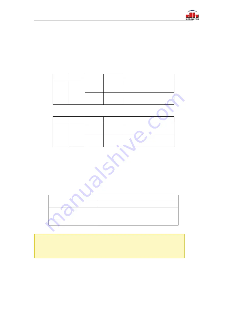
Table 3.1(a) Input 1 State
Pinout
Function
INPUT 1
Pin state
Perform action
INPUT 1
Position
High
resistance
0
Target position 1,target
force 1,target speed 1
0V
1
Target position 2,Target
Force 2,Target Speed 2
Table 3.1(b) Input 2 State
Pinout
Function
INPUT 1
Pin state
Perform action
INPUT 2 Rotation
High
resistance
0
Rotation angle 1, rotation speed 1,
rotation force 1
0V
1
Rotation angle 2, rotation speed 2,
rotation force 2
The input pin controls the position and rotation, and the
two pins have sequence
. According
to the actual situation, they can confirm whether they move first and then rotate or rotate and then
move.
You can also get the gripper state by detecting the states of Output1 and Output 2(0V and high
resistance states). as shown in Table 3.2.
Table 3.2 Output1 Output2 State
I/O
State
(OUT1 OUT2)
State description
0 0
Fingers are in motion
1 0
Fingers are at reference position,
No object detected or object has been dropped
0 1
Fingers have stopped due to an object detection
The four states of IO mode can be configured through Modbus RTU protocol of RS485, or the
parameters of gripper can be configured through our debugging software. Please refer to the
previous section for specific configuration mode. After the four groups of parameters are configured,
the gripper can be controlled by setting the Input 1 and Input 2 pin states, and the grip state can be
obtained by detecting the Output 1 and Output 2.
NOTE
·
Please make sure that the I/O hardware type of the gripper is compatible with your
controller’s.