After soldering the battery holder wires together cover the wire with a piece of shrink tube to
prevent short circuits. To do this, cut 2cm of the provided shrink tube, put it on the wire end and
heat it carefully with a lighter or your soldering iron. Heat the tube only for 1 second or less at the
time to prevent it from burning.
The battery holders are attached on the left and the right side of the robot body. Take the 3M foam
tape and cut one for each battery holder approximately 1cm x 1cm and stick it on the backside of
the battery holder opposite to the cable. Then remove the other protection layer and stick it on the
robot body, precisely on the front servo. Make sure the screw hole on the other side will align with
the hole in the center mounting piece. Use one of the screws (above in section 2 marked as
mounting screw) from the servos for each battery holder to secure it on the middle mounting piece.
6. Attaching the sensor holder and the IR sensor
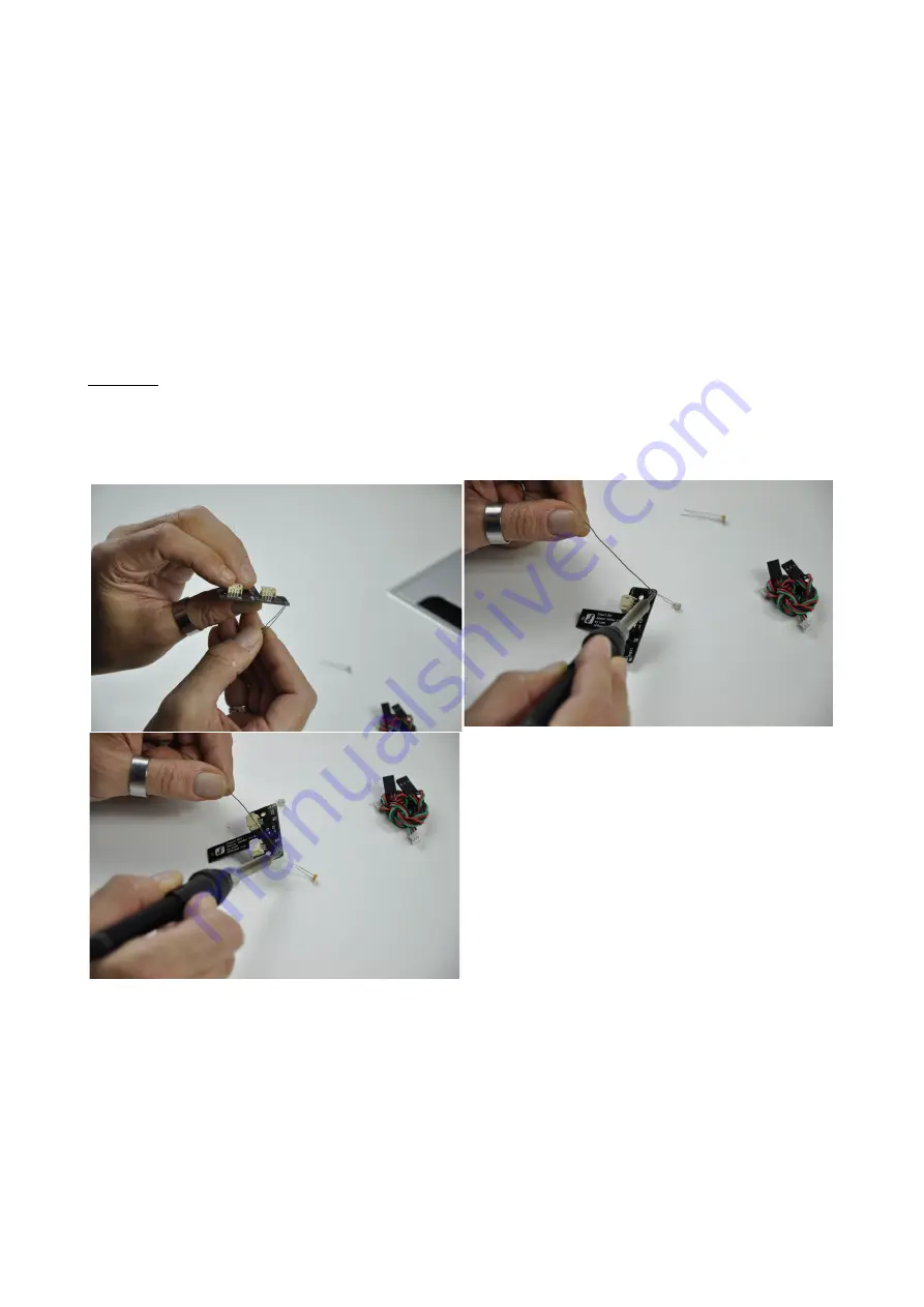
Optional: Solder the two LDR's (also called photo resistors) to the designated place on the sensor
holder. The two holes on the left and the right side of the sensor holder are labeled with LDR 1 and
LDR 2. After soldering the LDR's to the sensor holder cut 2cm length of shrink tube to cover the
sensors to avoid getting light from the side. Make sure that the two leads of the LDR are not
shorted.
Attach the sensor holder by fixing it with one of the supplied servo screws to the upper mounting
hole of the middle servo. Make sure you do not overturn the screw.
Use two of the cable ties to attach the IR sensor to the sensor holder. The connector of the IR sensor
may face up or down depending on your way to route the cable later.


