background image

www.dfi.com

11

Chapter 3 Installing the Devices

Chapter 3

Removing the Chassis Cover

Please observe the following guidelines and follow the procedure to open the system.

Chapter 3 - Installing the Devices

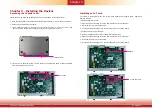
1. Make sure the system and all other peripheral devices connected to it have been powered off.

2. Disconnect all power cords and cables.

3. The 2 mounting screws on the bottom of the system are used to secure the cover to the 

chassis. Remove these screws and then put them in a safe place for later use.

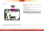
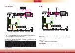
Chassis screw

4. Lift the cover to open the system. The M.2 socket on the expansion board is readily accessible 

after removing the bottom cover.

M.2 socekt

Installing an M.2 card

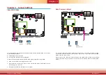
The system is equipped with one M.2 socket (SATA signals) and supports 42mm, 60mm and 

80mm M.2 SSDs.
To install an 80mm M.2 SSD:
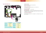
1.  Align the notch at the edge of the M.2 card with the key in the connector.
2.  Insert the M.2 card into the connector.
3.  Use the provided mounting screw to secure the card on the system board.

To install a 42mm or 60mm M.2 SSD:
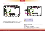
1.  Install the standoff at the 42mm or 60mm mounting position.
2.  Align the notch at the edge of the M.2 card with the key in the connector.
3.  Insert the M.2 card into the connector.

4.  Use the provided mounting screw to secure the card on the system board.

M.2 Type 2242 card

Standoff

Summary of Contents for EC70B-SU

Page 1: ...www dfi com 1 Chapter 1 Introduction EC70B SU User s Manual A 464 M 2008...

Page 2: ...owners FCC and DOC Statement on Class A This equipment has been tested and found to comply with the limits for a Class A digital device pursuant to Part 15 of the FCC rules These limits are designed t...

Page 3: ...ta 13 Auto Power on Select 13 Mini PCIe SATA Signal Select 14 COM4 DIO Select 14 Chapter 5 Ports and Connectors 15 Display Interfaces 15 USB Ports 16 COM Serial Ports 17 RJ45 LAN Ports 18 Audio 18 I O...

Page 4: ...ge can damage computer components without causing any signs of physical damage You must take extra care in han dling them to ensure against electrostatic build up 1 To prevent electrostatic build up l...

Page 5: ...rdinance Keep this system away from humidity Place the system on a stable surface Dropping it or letting it fall may cause damage The openings on the system are for air ventilation to protect the syst...

Page 6: ...o of them are PoE ports COM Six COM ports Display VGA or DP available upon request HDMI or DP available upon request Audio Microphone and Line out USB Six USB 3 0 Type A ports Power 15 36V DC in DIO 8...

Page 7: ...rectX 12 OpenCL 2 1 Supports these codecs HW Decode AVC H 264 MPEG2 VC1 WMV9 JPEG MJPEG HEVC H265 VP8 VP9 HW Encode AVC H 264 MPEG2 JPEG HEVC H265 VP8 VP9 Output displays VGA or DP resolution up to 19...

Page 8: ...ions Power on Switch Connects a power switch for distant power on off control Gigabit LAN Ports and PoE Ports Connect the system to a local area network The Power over Ethernet PoE ports are capable o...

Page 9: ...mensions Chapter 1 82 00 118 40 184 00 Front View Right View Left View Rear View Motherboard Dimensions 115 00 98 20 165 00 0 00 0 00 18 00 103 20 8 00 75 40 129 90 5 00 160 00 7 29 40 27 23 77 58 99...

Page 10: ...such as the date time and the type of hard disk drive 1 Power on the system 2 After the memory test the message Press DEL to run setup will appear on the screen Press the Delete key to enter the BIOS...

Page 11: ...he M 2 socket on the expansion board is readily accessible after removing the bottom cover M 2 socekt Installing an M 2 card The system is equipped with one M 2 socket SATA signals and supports 42mm 6...

Page 12: ...board and uninstall it from the system Use a wrench or a screwdriver with a socket end to remove the fasteners used on DB 9 and VGA connectors Use a wrench to remove the hexagonal gasket 1 Grasp the M...

Page 13: ...t JP3 JP4 Auto PWR ON JP1 JP2 JP7 You can reconfigure the system with the default values stored in the ROM BIOS if you encoun ter the following situations a CMOS data becomes corrupted b You forgot th...

Page 14: ...LAN 2 LAN 1 USB 2 USB 1 USB 3 0 USB 4 USB 3 COM 3 COM 2 COM 1 VGA USB 3 0 SATA 3 0 SPI Flash BIOS JP2 JP1 Battery EIO JP7 Mini PCIe MIC in LINE out HDMI SATA 2 SATA Power Realtek ALC888 Intel I210IT J...

Page 15: ...this VGA port will not be available Please refer to Display Interfaces expansion board below HDMI Port The HDMI port which carries both digital audio and video signals is used to connect the HDMI port...

Page 16: ...ion Wake On USB Keyboard Mouse The Wake On USB Keyboard Mouse function allows you to use a USB keyboard or USB mouse to wake up a system from the S3 STR Suspend To RAM state Important If you are using...

Page 17: ...DIO connector via jumper settings Refer to COM 4 DIO Select in Chapter 4 for its respective configuration 8 bit Digital IO The 8 bit Digital I O connector provides monitoring and control functions to...

Page 18: ...e hole connecting interface for inserting a plug Line out Jack This jack is used to connect a headphone or external speakers Mic in Jack This jack is used to connect an external microphone Driver Inst...

Page 19: ...in the Advanced menu SATA Configuration submenu of the BIOS Refer to Chapter 7 for more information Features SATA 3 0 6Gb s 7 RXN GND TXP TXN GND 1 RXP GND 12V 5V Ground 1 4 Ground DC in 1 80 6 1 1 1...

Page 20: ...M state it will blink every 4 seconds Power Standby LED PWR_LED This LED will blink when the system is in the standby mode It indicates that there is power on the system board Pin Pin Assignment Pin P...

Page 21: ...power cord prior to installing any devices Failure to do so will cause severe damage to the motherboard and components DC in 1 80 6 1 1 1 3 1 1 Mini PCIe 1 1 12 12 1 2 1 Reset Power Button Front Panel...

Page 22: ...the Advanced menu XCT5 2LPSE2C802U submenu of the BIOS Refer to Chapter 7 for more information LAN Ports expansion board PoE LED Speed LED LED Behavior Description LED Behavior Description Off The sy...

Page 23: ...l of the state of the connected external devices We have built support software called EAPI that enables the functionality of hardware components Please contact our technical support or sales represen...

Page 24: ...mation The display ports of the expansion board consist of the following 1 DP optional Display Interfaces expansion board 15 36V DC in DC out expansion board This DC in jack is considered a low power...

Page 25: ...rating system to use USB devices Refer to Chapter 8 for more information Wake On USB Keyboard Mouse The Wake On USB Keyboard Mouse function allows you to use a USB keyboard or USB mouse to wake up a s...

Page 26: ...e rubber feet are not attached to the chassis use these screw holes to mount wall brackets 2 Use the provided mounting screws to attach the wall mount brackets to both sides on the bottom of the syste...

Page 27: ...crews to attach both brackets to secure the system in place Mounting Screw The system VESA bracket A VESA bracket B Note The system unit used in the following illustrations may not resemble the actual...

Page 28: ...and put them in a safe place for later use 2 Align the mounting holes on the system and the mounting holes on the bracket and then use the screws removed in step 1 to secure the bracket in place 3 Th...

Page 29: ...screen The BIOS Setup Utility does not require an operating system to run After you power up the system the BIOS message appears on the screen and the memory count begins After the memory test the mes...

Page 30: ...econds from 00 to 59 System Date The date format is month date year Month displays the month from Janu ary to December Date displays the date from 1 to 31 Year displays the year from 1980 to 2099 Insy...

Page 31: ...in when power is re applied after a power fail ure G3 the mechanical off state S0 State The system is in working state S5 State The system is in soft off state CPU Configuration This section configure...

Page 32: ...e display at boot VGA HDMI or HDMI VGA The options may vary depending on the display ports wired on the device Primary Display Note that this configuration is only shown if the Boot Type is set to Dua...

Page 33: ...ces Disabled High definition audio devices will be unconditionally disabled Enabled High definition audio devices will be unconditionally enabled Auto High definition audio devices will be enabled if...

Page 34: ...SATA signal of the M 2 default or the CFast optional socket SATA Port 1 Controls the SATA signal of the half size mini PCIe slot SATA Port 2 Controls the SATA signal of the SATA port on the system boa...

Page 35: ...able or disable each PCI Express root port Intel I210 Controls the PCIe signal of the Intel I210IT controllers Mini PCIe Slot 1 Full Controls the PCIe signal of the full size Mini PCIe slot Mini PCIe...

Page 36: ...d Select the speed of the PCI Express Root Port Auto Gen1 2 5 GT s Gen2 5 GT s or Gen3 8 GT s ME Configuration This section configures flashing of the Intel Management Engine Me Fw Image Re Flash Enab...

Page 37: ...ort Enable or disable Intel Active Management Technology BIOS extension Un Configure ME Clears all ME related configurations without requiring a password on the next boot SIO NUVOTON6106D This section...

Page 38: ...ays on the sys tem s status will be power on after an AC power loss event ERP Support Enable or disable ERP Energy related Products support Disable the ERP support to allow the system to consume power...

Page 39: ...tup 39 XCT5 2LPSE2C8D2U The section allows you to configure the COM ports on the expansion board Serial Port 1 COM 5 and Serial Port 2 COM 6 Enable or disable each serial port Disable Disable this ser...

Page 40: ...the current state Disable Disable and deactivate TPM Enable Enable and activate TPM Clear TPM Remove all TPM ownership contents Set Supervisor Password Set the administrative password for entering th...

Page 41: ...lowing configuration options will be shown Device Name Select this option to set a password for the selected device Security Mode Description Lock HDD security status is enabled and locked Unlock HDD...

Page 42: ...Type PXE Boot Capability Dual Boot Type Enable or disable Preboot eXecution Environment PXE boot to LAN USB Boot Enable or disable booting to USB boot devices Boot Menu Normal For this option determin...

Page 43: ...BIOS setup utility Exit Saving Changes Select this field and press Enter to exit BIOS setup and save your changes Load Optimal Defaults Select this field and press Enter to load the optimal defaults...

Page 44: ...will not be updated and will cease to be effective Updating the BIOS To update the BIOS you will need the new BIOS file and a flash utility Please contact techni cal support or your sales representat...

Page 45: ...r Once you are in the Download Center page select your product or type the model name and click Search to find product related resources such as documentation and drivers Drivers are available for the...

Page 46: ...he system To install the utility follow these steps 1 Setup is ready to install the utility Click Next 2 Read the license agreement and then click Yes 5 Click Restart Now to allow the new software ins...

Page 47: ...ning before the Windows 7 Windows 8 1 Windows 10 desktop appears The blank screen period is the time Windows is testing the graphics performance We recommend that you skip this process by disabling th...

Page 48: ...is preparing to install the driver Click Next to continue 2 Click I accept the terms in the license agreement if you accept the agreement and then click Next 3 Select the program features you want to...

Page 49: ...now 3 Click Restart Now to restart your computer when the installation is complete Intel USB 3 0 Driver For Windows 7 and Windows 8 1 To install the driver click Intel USB 3 0 Driver on the main menu...

Page 50: ...r follow these steps 1 You are about to install the driver Click Next to continue 2 Read the license agree ment and then click Next 4 Please wait while the prod uct is being installed 5 After the inst...

Page 51: ...mputer now and then click Finish Restart the system to allow the new software installation to take effect Audio Driver To install this driver follow these steps Serial IO Driver To install this driver...

Page 52: ...upported Software www dfi com 4 Setup is ready to install the driver Click Next to begin the installation 3 Read the file information and then click Next 5 Setup is now installing the driver 6 Click F...

Page 53: ...ducing desk side visits Repair Remotely repair systems after OS failures Alerting and event logging help detect problems quickly to reduce downtime Protect Intel AMT s System Defense capability remote...

Page 54: ...ngine BIOS Extension MEBX 1 After the system reboots press Del to enter the BIOS menu again 2 In the Advanced menu select MEBX Configuration to enter the Manageability Engine BIOS Extension MEBx Setup...

Page 55: ...de 8 32 characters Strong 7 bit ASCII characters excluding and characters At least one digit character 0 1 9 At least one 7 bit ASCII non alpha numeric character above 0x20 e g Both lower case and upp...

Page 56: ...ault password is admin Enter the default password in the space provided under Intel R ME New Password and then press Enter 8 32 characters Strong 7 bit ASCII characters excluding and characters At lea...

Page 57: ...sion Remote Setup And Configuration Power Control INTEL R AMT CONFIGURATION Move Highlight Enter Select Entry Esc Exit 10 In the Intel R AMT Configuration menu select Manageability Feature Selection...

Page 58: ...enu select Storage Redirection and then press Enter Select Enabled or Disabled and then press Enter 15 In the SOL IDER KVM menu select KVM Feature Selection and then press Enter Select Enabled or Disa...

Page 59: ...ttings TCP IP Settings 18 In the User Consent menu select Opt in Configurable from Remote IT and then press Enter Select Enabled or Disable Remote Control of KVM Opt in Policy and then press Enter 19...

Page 60: ...hanges 22 In the Intel R ME Network Name Settings menu select Host Name and then press Enter Enter the computer s host name and then press Enter 23 Select Domain Name and then press Enter Enter the co...

Page 61: ...Setup And Configuration Power Control Activates the current network settings and opens the ME network interface Continue Y N 26 Select Previous Menu until you return to the Intel R ME Network Setup me...

Page 62: ...PV4 IPV6 _ Provisioning Server FQDN _ RCFG TLS PKI Move Highlight Enter Select Entry Esc Exit Provisioning server address 30 In the Intel R AMT Configuration menu select Remote Setup And Configuration...

Page 63: ...Configuration menu select Provisioning server FQDN enter the FQDN of Provisioning server and then press Enter 35 In the Intel R Remote Setup And Configuration menu select RCFG and press Enter and the...

Page 64: ...t CA 2 Entrust Root CA VeriSign Universa Go Daddy Root CA Entrust Root CA Startfield Root CA Move Highlight Enter Select Entry Esc Exit Manageability Feature Selection Enabled SOL Storage Redirection...

Page 65: ...s Timeout Value 1 65535 65535 INTEL R AMT POWER CONTROL Desktop ON in S0 Desktop ON in S0 ME Wake in S3 S4 5 Intel R AMT ON in Host Sleep States Desktop ON in S0 ME Wake in S3 S4 5 Idle Timeout 65535...

Reviews: