background image

49

Chapter 4

INTEL AMT SETTINGS

User's Manual | 

EB100-KU

MEBx Exit

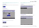
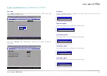
Under the Main Menu, select MEBx Exit and then press Enter. Press Y to confirm or N to abort.

Intel(R) Management Engine BIOS Extension v11.0.0.0010/Intel(R) ME v11.8.55.3510

Copyright(C) 2003-16 Intel Corporation. All Rights Reserved

MAIN MENU

[

↑↓

] =Move Highlight     [Enter] =Select Entry           [Esc] =Exit

Are you sure you want to exit?(Y/N):

> Intel(R) ME General Settings

> Intel(R) AMT Configuration

MEBx Exit

         Exit


X

MEBX

Summary of Contents for EB100-KU

Page 1: ...EB100 KU Fanless Embedded System User s Manual A 529 M 2026 Preliminary Version...

Page 2: ...FCC and DOC Statement on Class B This equipment has been tested and found to comply with the limits for a Class B digital device pursuant to Part 15 of the FCC rules These limits are designed to provi...

Page 3: ...In 18 Battery 19 SATA Serial ATA Connector 19 Expansion Slots 20 Installing the Mini PCIe Module 20 Chapter 3 BIOS Settings 22 Overview 22 Main 23 Advanced 23 ACPI Configuration 24 CPU Configuration...

Page 4: ...point factory or authorized ser vice agency for all such work 4 We will not be liable for any indirect special incidental or consequencial damages to the product that has been modified or altered Abou...

Page 5: ...r objects to make sure of proper air ventilation to protect the system from over heating Dress the cables especially the power cord so they will not be stepped on in contact with high temperature surf...

Page 6: ...6x2304 24Hz Dual Displays HDMI STORAGE Internal 512GB M 2 SSD EXPANSION Interface 1 x Half size Mini PCIe socket PCIe USB 2 0 ETHERNET Controller 1 x Intel I210AT 10 100 1000Mbps 1 x Intel I219LM 10 1...

Page 7: ...00 KU Chapter 2 Hardware Installation X Overview Front Panel Rear Panel Dimensions 2 x USB 2 0 SSD LED Reset 4 x USB 3 0 Power Button with LED Audio Out Mic In 2 x HDMI Ground 12V DC In LAN1 LAN2 111...

Page 8: ...Place the system top side down on a stable worksurface Locate the mounting holes on the bottom of the system and the bracket and make sure them align Screw the brackets onto the system with four screw...

Page 9: ...on the back of a monitor a stand or a wall rack that conforms to VESA mounting Attache the two step screws to the bottom side of the system as illustrated Mount the assembly onto the VESA mount brack...

Page 10: ...metal cover and the 2 5 SATA drive tray are secured onto the chassis with 4 screws that go through the front and rear panel metals Use a Phillips screwdriver to unscrew them The cable for SATA data an...

Page 11: ...the side cover The rear panel is also secured by the DC In connector as shown below Front Panel Top side Down Front Panel Top side Down Place the assembly top side down on a stable worksurface Attache...

Page 12: ...d below Please make sure the side cover metal piece is oriented correctly by aligning the inden tation to that on the top cover A A B B Place the assembly top side down on a stable worksurface Place t...

Page 13: ...ollowing safety cautions are well attended 1 Make sure the PC and all other peripheral devices connected to it has been powered down 2 Disconnect all power cords and cables Connect the internal cable...

Page 14: ...procedures requiring ESD protection X Board Layout System Board Audio Out and Mic In HDMI1 and HDMI2 LAN2 LAN1 12V DC In Power Button Reset Button and SSD LED Clear CMOS JP1 USB 6 7 USB 2 0 USB 3 4 US...

Page 15: ...mory card is aligned to the key on the socket The system board supports the following memory interface Single Channel SC Data will be accessed in chunks of 64 bits from the memory channels Dual Channe...

Page 16: ...that the clip sits in the notch If not please pull the clips outward release and remove the card and mount it again Key Socket Top View Retention Clip 45 Step 1 Step 2 Step 3 X System Memory X Jumper...

Page 17: ...ween your computer and a wide range of simultaneously acces sible external Plug and Play peripherals The system board is equipped with multiple USB Type A ports at the front panel four USB 3 0 and two...

Page 18: ...EBX Refer to Chapter 4 for more information Features LAN1 1 x Intel I219LM 10 100 1000Mbps LAN2 1 x Intel I210AT 10 100 1000Mbps Rear Panel Rear Panel LAN1 LAN1 LAN2 1 1 12V DC In Connect the power so...

Page 19: ...A Connector X I O Ports Battery The external lithium ion battery supplies power to the real time clock and CMOS memory as an auxiliary source of power when the main power is shut off Safety Measures T...

Page 20: ...tate storage The board preserves space and a standoff for the M 2 M key socket 22mm x 80mm The M 2 M key supports SATA PCIe and reset signals Mini PCIe M 2 M Key Before installing the Mini PCIe module...

Page 21: ...e socket down until against the stand off Step 3 Screw tight the card onto the stand off with a screw driver and a stand off screw until the gap between the card and the stand off closes up The card s...

Page 22: ...not require an operating system to run After you power up the system the BIOS message appears on the screen and the memory count begins After the memory test the message Press DEL to run setup will a...

Page 23: ...nute second The time is based on the 24 hour military time clock For example 1 p m is 13 00 00 Hour displays hours from 00 to 23 Minute displays min utes from 00 to 59 Second displays seconds from 00...

Page 24: ...ff after power failure Power on signal input is re quired to power up the system Wake On RTC When Enabled the system will automatically wake up from S4 S5 state at a designated time every day via the...

Page 25: ...nagement It allows CPU to go to C States when it s not 100 utilized Hyper threading Enable or disable Hyper threading When it is enabled a physical core will perform as two logical processors and the...

Page 26: ...nter Select SubMenu F9 Setup Defaults F10 Save and Exit Enable or Disable SATA Device SATA Controller s SATA Speed SATA Mode Selection SATA0 Port 0 Hot Plug M 2 M Port 2 Hot Plug Enabled Auto AHCI Not...

Page 27: ...t Select Item Select Item F5 F6 Change Values Enter Select SubMenu F9 Setup Defaults F10 Save and Exit InsydeH2O Setup Utility Rev 5 0 F1 Help Esc Exit Select Item Select Item F5 F6 Change Values Ente...

Page 28: ...sydeH2O Setup Utility Rev 5 0 F1 Help Esc Exit Select Item Select Item F5 F6 Change Values Enter Select SubMenu F9 Setup Defaults F10 Save and Exit Mini PCIE Settings Mini PCIE GLAN WGI219LM GLAN WGI2...

Page 29: ...port Intel AMT Support Enabled Enable AMT When this field is enabled the user is allowed to configure AMT settings via MEBX Disabled Disable AMT When this field is disabled AMT settings cannot be conf...

Page 30: ...dvanced Exit BIOS Setup Utility and launch Device Manager OK Press Enter and OK to enter UEFI Device Manager setup page More device settings can be configured in the UEFI Device Manager including LAN...

Page 31: ...vailability Available Hidden Security X Security X Boot InsydeH2O Setup Utility Rev 5 0 F1 Help Esc Exit Select Item Select Item F5 F6 Change Values Enter Select SubMenu F9 Setup Defaults F10 Save and...

Page 32: ...k Drive CD DVD ROM Drive USB Others Arrange the priority of the storage devices in each category The submenu will not be displayed when there is no available storage device of the type Legacy Configur...

Page 33: ...according to the type of the storage devices and the configured order Advance Boot priority is arranged according to the configured order regardless of the type of the storage devices Boot Type Order...

Page 34: ...l not be up dated and will cease to be effective Note a You can take advantage of flash tools to update the default configuration of the BIOS SPI ROM to the latest version anytime b When the BIOS IC n...

Page 35: ...ly alerting when critical software agents are removed X Enable Intel AMT in the Insyde BIOS 1 Power on the system then press Del to enter the main menu of the Insyde BIOS 2 In the Advanced menu select...

Page 36: ...yde BIOS 2 In the Advanced menu select MEBX Configuration 3 Select MEBX Configuration and press Enter InsydeH2O Setup Utility Rev 5 0 F1 Help Esc Exit Select Item Select Item F5 F6 Change Values Enter...

Page 37: ...ights Reserved MAIN MENU MEBx Login Intel R ME General Settings Intel R AMT Configuration MEBx Exit Intel R ME Password Move Highlight Enter Select Entry Esc Exit Intel R ME Password X MEBX Main Menu...

Page 38: ...press Enter Intel R Management Engine BIOS Extension v11 0 0 0010 Intel R ME v11 8 55 3510 Copyright C 2003 16 Intel Corporation All Rights Reserved INTEL R ME PLATFORM CONFIGURATION Change ME Passwo...

Page 39: ...ght C 2003 16 Intel Corporation All Rights Reserved Manageability Feature Selection Enabled SOL Storage Redirection KVM User Consent Password Policy Anytime Network Setup Activate Network Access Uncon...

Page 40: ...o display options Username and Password Select Enabled or Disabled then press Enter SOL Select Enabled or Disabled then press Enter Storage Redirection Select Enabled or Disabled then press Enter KVM...

Page 41: ...on menu select Password Policy then press Enter You may choose to use a password only during setup and configuration or to use a password anytime the system is being accessed Intel R Management Engine...

Page 42: ...010 Intel R ME v11 8 55 3510 Copyright C 2003 16 Intel Corporation All Rights Reserved Enter Complete Entry Esc Discard Changes INTEL R ME NETWORK NAME SETTINGS Host Name Domain Name Shared Dedicated...

Page 43: ...ights Reserved INTEL R ME NETWORK NAME SETTINGS Host Name Domain Name Shared Dedicated FQDN Dynamic DNS Update Periodic Update Interval TTL Enter Complete Entry Esc Discard Changes _ _ Shared Enabled...

Page 44: ...0 0 Preferred DNS Address 0 0 0 0 Alternate DNS Address 0 0 0 0 Enter Complete Entry Esc Discard Changes Subnet Mask Address Insert a value from 0 0 0 0 to 255 255 255 255 in IPv4 format Default Gate...

Page 45: ...TION Move Highlight Enter Select Entry Esc Exit Manageability Feature Selection Enabled SOL Storage Redirection KVM User Consent Password Policy Anytime Network Setup Activate Network Access Unconfigu...

Page 46: ...e current mode Public Key Infrastructure PKI is displayed Intel R Management Engine BIOS Extension v11 0 0 0010 Intel R ME v11 8 55 3510 Copyright C 2003 16 Intel Corporation All Rights Reserved Move...

Page 47: ...yption and authentication and the TLS protocol for communica tion security to ensure remote configuration safety Remote Configuration Select Enabled or Disabled then press Enter Intel R Management Eng...

Page 48: ...ult Default Default Default Default Default Default Default Default Default Default Default SHA256 SHA256 SHA256 SHA256 SHA256 SHA256 SHA256 SHA256 SHA256 SHA256 SHA256 SHA256 SHA256 SHA256 SHA256 SHA...

Page 49: ...Y to confirm or N to abort Intel R Management Engine BIOS Extension v11 0 0 0010 Intel R ME v11 8 55 3510 Copyright C 2003 16 Intel Corporation All Rights Reserved MAIN MENU Move Highlight Enter Sele...

Reviews: