


NOTE:
Proper grounding of the ignition
system (yellow wires) is very critical
for proper ignition sequence.
Ignition System-Function & Sequence
During normal dryer operation, the following occurs:
1. The dryer electronic control calls for heat.
2. If the drive motor is running, the motor safety
circuit provides power to the electronic control. If
the control senses that the heat should be on, a
circuit is closed allowing power through the high
limit thermostat and air flow switch to the ignition
transformer. The transformer provides 24VAC to
the ignition module and sparking occurs at the
ignition electrode. At the same time 24VAC is
applied to the gas valve.
3. Once the flame is established, the sensing electrode detects the presence of flame and the
sparking stops.
4. If for any reason the flame is not established in a period of 10 seconds, the electronic control
will try this sequence for 3 tries. Normally the 10 seconds “Trial For Ignition” period is ample to
establish and prove flame.
5. If the flame is shutdown or blown out during operation, the ignitor will imm.ediately go into “Trial
For Ignition” again for 10 seconds.
6. However,at the end of 3 separate retries of 10 seconds “Trial for Ignition”, the flame is not
established, the ignition system goes into “Safety Lock-Out” and will not reactivate the “Trial for
Ignition” until there is a current interruption for a period of 15 seconds. This interruption can be
provided by opening the dryer loading door and allowing the machine to come to a complete stop
for 15 seconds.
Ignition System-Checkout
1. If flame is present during “Trial For Ignition” period but the system shuts down, there may be
an improper ground. The entire ignition system is grounded together including the electrode
assembly, the electrode mounting bracket, the burners and the burner bracket. Shutdown can
also occur if for some reason the system isn’t sensing the flame. Check the sensor for damage
and check the connections of the sensor lead.
2. If there is no spark or intermittent spark, check black hi-voltage lead wire for damage or cracks in
insulation. (This lead wire must not be taped or connected to any metal edges along its length to
prevent pinching and arcing. Also, do not bundle this wire with other wires.)
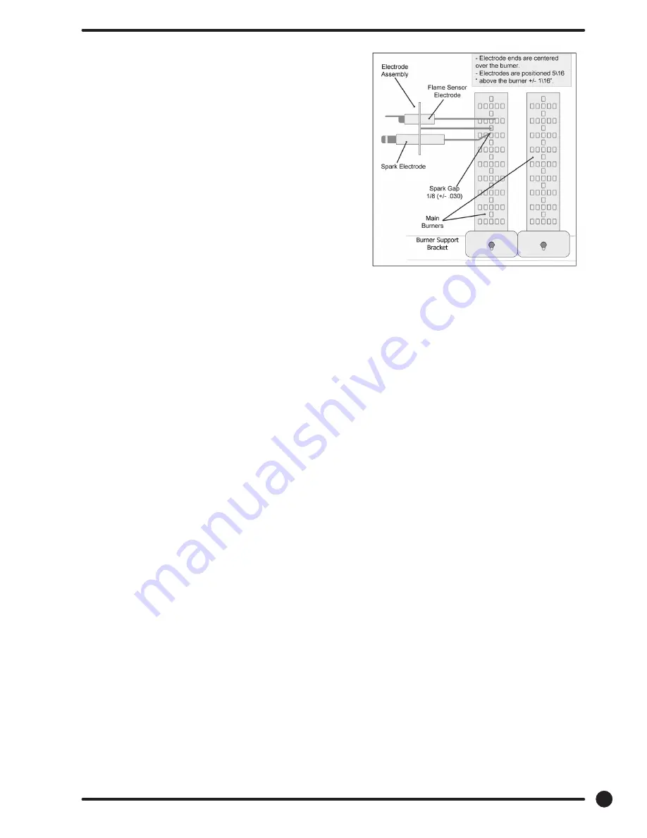
NOTE:
Spark gap and electrode location are important. If the electrode is damaged
or mounting is changed the spark gap may not be correct for ignition to
occur. Check for cracks in the ceramic insulator. Replace electrode assembly
if necessary. Also check for carbon or foreign material on the electrodes
and clean if necessary.
63
Part # 8533-090-001 7/21
Summary of Contents for DC30X2 Series
Page 9: ...9 Part 8533 090 001 7 21 Notes ...
Page 12: ...12 Part 8533 090 001 7 21 Notes ...
Page 13: ...13 Part 8533 090 0001 7 21 Section 1 Specifications ...
Page 15: ...Dexter T30x2 Stack Dryer Installation Dimensions 15 Part 8533 090 001 7 21 ...
Page 16: ...16 Part 8533 090 001 7 21 Notes ...
Page 17: ...Section 2 Installation Operation 17 Part 8533 090 0001 7 21 ...
Page 24: ...24 Part 8533 090 001 7 21 Notes ...
Page 25: ...25 Part 8533 090 0001 7 21 Section 3 Programing C Series Stack Dryer ...
Page 41: ...41 Part 8533 090 001 7 21 The figure below shows the sub menu options for Prices ...
Page 43: ...43 Part 8533 090 001 7 21 ...
Page 47: ...47 Part 8533 090 001 7 21 The figure below shows the sub menu options for Settings ...
Page 50: ...50 Part 8533 090 001 7 21 Notes ...
Page 51: ...51 Part 8533 090 0001 7 21 Section 4 Schematic C Series Stack Dryer ...
Page 54: ...Wiring Diagram for DC30x2 54 Part 8533 090 001 7 21 ...
Page 55: ...Wiring Schematic for DC30x2 55 Part 8533 090 001 7 21 ...
Page 56: ...56 Part 8533 090 001 7 21 Notes ...
Page 57: ...57 Part 8533 090 0001 7 21 Section 5 Service Procedures ...
Page 66: ...66 Part 8533 090 001 7 21 Notes ...
Page 67: ...67 Part 8533 090 0001 7 21 Section 6 Troubleshooting C Series Stack Dryer ...
Page 76: ...76 Part 8533 090 001 7 21 Notes ...
Page 77: ...77 Part 8533 090 0001 7 21 Section 7 Parts Data DC30X2 24VAC Control ...
Page 78: ...1 2 6 5 4 3 13 8 12 11 7 1 9 6 5 4 3 10 11 2 10 12 9 78 Part 8533 090 001 7 21 ...
Page 81: ...20 21 19 18 17 16 15 14 22 25 26 24 23 19 25 26 27 28 81 Part 8533 090 001 7 21 ...
Page 82: ...1 9 2 6 5 4 3 10 8 12 11 7 9 82 Part 8533 090 001 7 21 ...
Page 85: ...85 Part 8533 090 001 7 21 Notes ...
Page 93: ...1 6 5 4 7 1 8 93 Part 8533 090 001 7 21 ...
Page 98: ...Wiring Diagram for DC30x2 98 Part 8533 090 001 7 21 ...
Page 99: ...Wiring Schematic for DC30x2 99 Part 8533 090 001 7 21 ...
Page 100: ...100 Part 8533 090 001 7 21 Notes ...
Page 101: ...101 Part 8533 090 0001 7 21 Section 8 Maintenance ...
Page 103: ...103 Part 8533 090 0001 7 21 Section 9 Voltage Conversion ...
Page 104: ... 104 Part 8533 090 001 7 21 ...
Page 105: ... 105 Part 8533 090 001 7 21 ...
Page 106: ...106 Part 8533 090 001 7 21 Notes ...
Page 107: ...107 Part 8533 090 001 7 21 Section 10 50 hZ Models ...
Page 108: ...108 Part 8533 090 001 7 21 Notes ...
Page 113: ...1 2 4 3 1 113 Part 8533 090 001 7 21 7 ...
Page 115: ...115 Part 8533 090 001 7 21 Notes ...
Page 116: ...1 9 2 6 5 4 3 10 8 7 9 116 Part 8533 090 001 7 21 ...
Page 118: ...118 Part 8533 090 001 7 21 ...
Page 120: ...120 Part 8533 090 001 7 21 ...
Page 121: ...IMPORTANT RETAIN THIS ELECTRICAL DIAGRAM FOR SERVICE 121 Part 8533 090 001 7 21 ...
Page 122: ...RETAIN THIS ELECTRICAL DIAGRAM FOR SERVICE 122 Part 8533 090 001 7 21 ...
Page 123: ...DPY 123 Part 8533 090 001 7 21 ...
Page 124: ...124 Part 8533 090 001 7 21 Notes ...


