IOLite LX Quick Start
TECHNICAL REFERENCE MANUAL
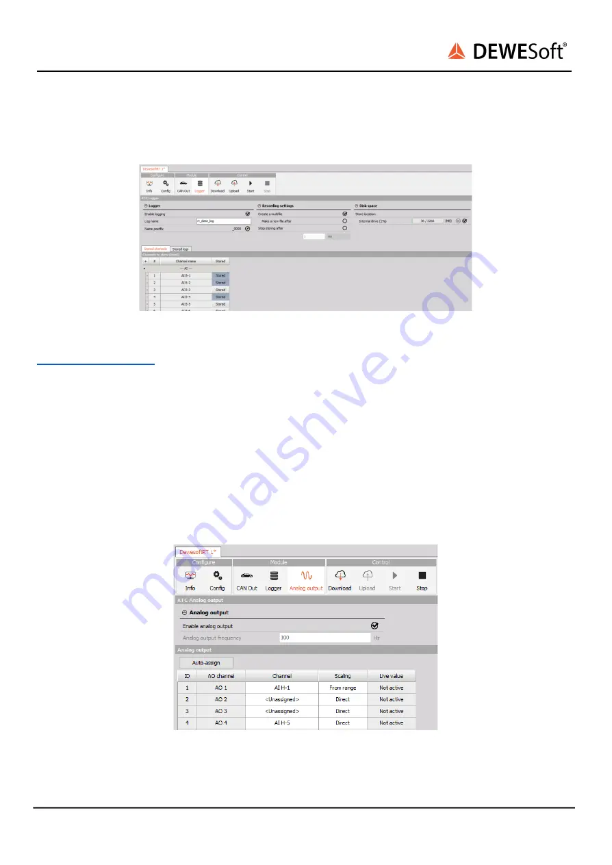
In the bottom of the interface you can see the list of the channels available and define which ones
should be stored, or switch to the stored logs view, where you can see the list of all the stored data files
on the currently selected location.
Image 14: Logger module
To view the logged data, it needs to be imported into Dewesoft first, which is described in the chapter
9.2.3. Analog output
The last module available here is the “Analog output” module. This module takes care of outputting the
measured values through the optional analog outputs if the IOLite LX is configured with the needed
hardware.
Here you can enable the output functionality and define which input channel should be output on
which analog output channel. You can also define the scaling, where “Direct” means 1:1 output, so if
input is 5 V then also the output will be 5 V. The other option, “From range”, means that the output
range will be matched to the range, so if the input module range is ±100 V and the measured value is 50
V, it will match the input range to the output range of ±10 V and will therefore output 5 V.
Image 15: Analog output module
IOLite LX Quick Start V21-1
12/32


