background image

6

DXST4500

P

AR

TS LIST

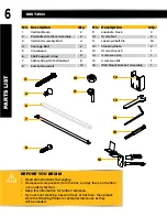
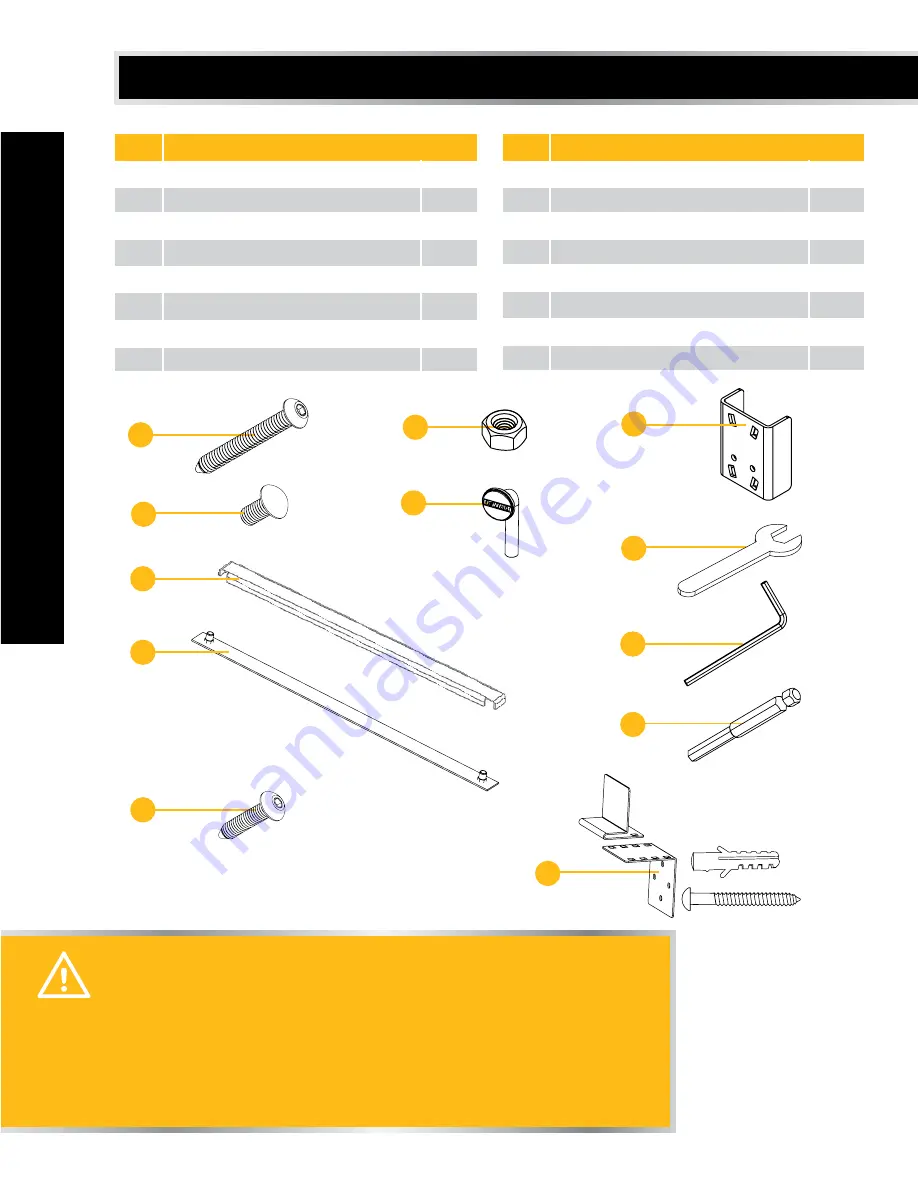
No. Description

1

Vertical Beam

2

Pre-Bolted Vertical Assembly

3

Vertical Assembly Bolt

4

Carriage Bolt

5

Crossbeam

6

Shelf Support Strap

7

Safety Strap With Weld Nut

8

Safety Strap Bolt

No. Description

9

Laminate Deck  

10

10 mm Nut

11

Locking Shelf Pin

12

Stacking Plate

13

10 mm Wrench

14

4 mm Hex Key

15

4 mm Hex Bit

16

Wall Mount Bracket Assembly

4

3

BEFORE YOU BEGIN:

•  Read all instructions thoroughly.
•  Remove all components from the box, and lay them on the floor 

in an orderly fashion.

•  Keep this information for further reference.
•  If you are not stacking a second rack at this time, then please 

store the Stacking Plates for potential future use as they

     will be needed.

FPO

6

7

11

12

13

14

15

16

2
2
4
2
6
9
6
12

3
2
16
2
1
1
1
1

Qty.

Qty.

10

8

Summary of Contents for DXST4500

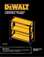
Page 1: ...IMPORTANT Please read this manual carefully before assembling this storage rack and save it for reference DXST4500 TITAN INDUSTRIAL RACK 4 FOOT TALL 3 SHELF INSTRUCTION MANUAL ...

Page 2: ......

Page 3: ...al contains important safety and operating instructions Read all instructions and follow them with use of this product TABLE OF CONTENTS TECHNICAL SPECIFICATIONS 4 SAFETY 5 PARTS LIST 6 ASSEMBLY 8 OPTIONS 13 WARRANTY 14 TABLE OF CONTENTS ...

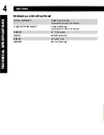
Page 4: ...OTAL CAPACITY 4 500 lb 2 041 kg WHEN WEIGHT IS EVENLY DISTRIBUTED CAPACITY PER SHELF 1 500 lb 680 kg WHEN WEIGHT IS EVENLY DISTRIBUTED HEIGHT 47 119 4 cm WIDTH 49 5 8 126 cm DEPTH 18 45 7 cm WEIGHT 80 7 lb 36 6 kg TECHNICAL SPECIFICATIONS ...

Page 5: ...r crawl sit stand or climb on the rack Keep small parts away from children Never leave a small child unattended while assembling Always use common sense your personal safety is your responsibility SPECIFIC SAFETY FOR WALL MOUNT BRACKET Serious injury or death can occur from the rack tipping over To prevent this the rack must be secured to a wall especially in earthquake prone areas or where surfac...

Page 6: ...tacking Plate 13 10 mm Wrench 14 4 mm Hex Key 15 4 mm Hex Bit 16 Wall Mount Bracket Assembly 4 3 BEFORE YOU BEGIN Read all instructions thoroughly Remove all components from the box and lay them on the floor in an orderly fashion Keep this information for further reference If you are not stacking a second rack at this time then please store the Stacking Plates for potential future use as they will...

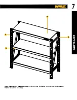
Page 7: ...7 2 1 PARTS LIST Tools Required for Rack Assembly 4 mm Hex Key included OR 4 mm Hex Bit included Rubber Mallet not included 9 5 ...

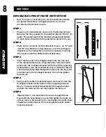
Page 8: ...into the free end of the top horizontal beam Align the holes and insert both beams into the U shaped bracket at the top of the opposing Vertical Beam Use the included hex key or drill bit to thread a Vertical Assembly Bolt through the holes and into the weld nut attached to the U shaped bracket Do not fully tighten the bolt yet STEP 4 Swing out the bottom horizontal beam and insert it into the U s...

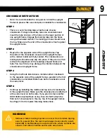
Page 9: ...ame STEP 2 Repeat for the opposite side of the upright frame Tap the ends of the crossbeam closest to the upright frames with a rubber mallet until fully seated The crossbeam and locking tabs should easily slip into place If they do not then recheck the alignment of the teardrop shaped holes and tabs Too much force may damage the interlock between the crossbeam and upright frame STEP 3 Using the m...

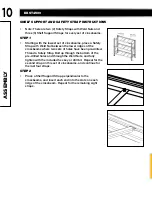
Page 10: ...have been pre drilled Thread a Safety Strap Bolt up through the bottom of the pre drilled holes and through the Weld Nuts and fully tighten with the included hex key or drill bit Repeat for the second strap on this set of crossbeams and continue for the last four straps STEP 2 Place a Shelf Support Strap perpendicular to the crossbeams and insert each end into the slots on each ridge of the crossb...

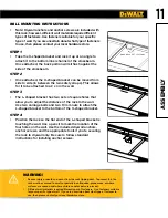
Page 11: ...ou to adjust the distance of the rack to the wall Use two carriage bolts and two 10 mm nuts to attach the L shaped bracket to the bottom of the U shaped bracket STEP 4 Position the rack so the flat end of the L shaped bracket is touching the wall Use a pencil to mark the location of the four holes on the wall Use the included drywall anchors anchor screws and the appropriate tools if you re securi...

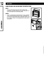
Page 12: ...at for the remaining decks STEP 2 There is a locking pin hole at both ends of every crossbeam This is where the locking shelf pins are to be installed If a pin does not easily slip into place moderately tap the end of the crossbeam closest to the upright frame to fully seat the locking tabs ASSEMBLY LAMINATE DECK AND LOCKING SHELF PIN INSTRUCTIONS ...

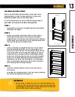
Page 13: ...mbled rack Be sure the hole patterns are going in the same direction The stacking brackets feature a top and bottom set of locking tabs Engage the top set of tabs into the very bottom of the vertical beam and the bottom set of locking tabs into the very top of the upright frame Use the same downward motion to attach these brackets as you did for the crossbeams The locking pin holes on the bracket ...

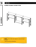
Page 14: ...DXST4500 14 MAXIMIZE YOUR DEWALT STORAGE OPTIONS NOTE Connect multiple racks together to increase both length and height Additional racks are sold separately ASSEMBLY ...

Page 15: ...y coverage call 1 844 377 8451 In addition to the warranty DEWALT tools are covered by our 90 DAY MONEY BACK GUARANTEE If you are not completely satisfied with the performance of your DEWALT Industrial Rack for any reason you can return it within 90 days from the date of purchase with a receipt for a full refund no questions asked LATIN AMERICA This warranty does not apply to products sold in Lati...

Reviews: