background image

8

English

MAINTENANCE

Your power tool has been designed to operate over a long 
period of time with a minimum of maintenance. Continuous 
satisfactory operation depends upon proper tool care and 
regular cleaning.


WARNING:


To reduce the risk of serious personal 

injury, turn tool off and disconnect tool from power 
source before making any adjustments or removing/
installing attachments or accessories. 

An accidental 

start‑up can cause injury.

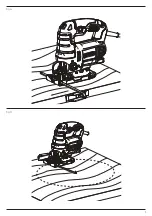
Rip/Circle Cutting (Fig. G, H)

Ripping and circle cutting without a pencil line is easily done with 
the rip fence / circle guide (not included; available at extra cost).
Using the screw supplied with the accessory guide, position and 
thread the screw into the shoe to clamp the fence securely.
When ripping, slide the rip fence under the screw from either 
side of the saw. Set the cross bar at desired distance from blade 
and tighten screw. For ripping, the cross bar should be down and 
against the straight edge of the workpiece.
When circle cutting, adjust rip fence so that distance from blade 
to hole in fence arm is at the desired radius and tighten screw. 
Place saw so that hole in fence arm is over center of circle to be 
cut (drill hole for blade or cut inward from edge of material to 
get blade into position). When saw is properly positioned, drive 
a small nail through hole in fence arm. Using rip fence as a pivot 
arm, begin cutting circle. For circle cutting, the cross bar should 
be up.

Hints for Optimum Use

Sawing laminates

As the saw blade cuts on the upward stroke, splintering may 
occur on the surface closest to the shoe plate.
Use a fine‑tooth saw blade.
Saw from the back surface of the workpiece.
To minimize splintering, clamp a piece of scrap wood or 
hardboard to both sides of the workpiece and saw through 
this sandwich.

Sawing metal

•  Be aware that sawing metal takes much more time than 

sawing wood.

•  Use a saw blade suitable for sawing metal.
•  When cutting thin metal, clamp a piece of scrap wood to the 

back surface of the workpiece and cut through this sandwich.

•  Spread a film of oil along the intended line of cut for easier 

operation and longer blade life. For cutting aluminum, 
kerosene is preferred.

To attach shoe sleeve, place the front of the shoe 

 6 

 into the 

front of the shoe sleeve and lower the jig saw as shown in 
Figure F

The shoe sleeve will click securely onto the rear of 

the shoe.
To remove shoe sleeve, grasp the sleeve from the bottom at the 
two rear tabs and pull down and away from the shoe.

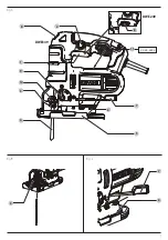
Removable Shoe Sleeve (Fig. F)

The non‑marring shoe sleeve 

 5 

 should be used when cutting 

surfaces that scratch easily, such as laminate, veneer, or 
paint. It can also be used to protect the shoe surface during 
transportation and storage.

Cutting Action – Orbital or Straight (Fig. A)


WARNING:

 Check that the tool is not locked ON before 

connecting it to a power supply. If the trigger switch is 
locked on when the tool is connected to the power supply, 
it will start immediately. Damage to your tool or personal 
injury may result.

This jig saw is equipped with four cutting actions, three orbital 
and one straight. Orbital action has a more aggressive blade 
motion and is designed for cutting in soft materials like wood 
or plastic. Orbital action provides a faster cut, but with a less 
smooth cut across the material. In orbital action, the blade 
moves forward during the cutting stroke in addition to the up 
and down motion.

nOTE: 

Metal or hardwoods should never be cut in orbital action.

Setting the Pendulum Stroke

1.  Move the pendulum stroke selectorr 

 9 

 between the four 

cutting positions: 0, 1, 2, and 3.

2.  Position 0 is straight cutting.
3.  Positions 1, 2, and 3 are orbital cutting.

The aggressiveness of the cut increases as the lever is adjusted 
from one to three, with three being the most aggressive cut.

Variable Speed Control (Fig. A, E)


WARNING:

 If the tool is operated continuously at low 

speeds for a long time, the motor will get overload and 
heated up.

A speed control dial 

 8 

 is located on the trigger for the DWE249 

and on the top of the saw for the DWE349. The speed increases 
as the dial is turned from a low speed setting of 1 to a high 
speed setting of 6.
Refer to the table to select the proper speed for the workpiece 
to be cut. However, the appropriate speed may differ with the 
type or thickness of the workpiece. In general, higher speeds 
will allow you to cut workpieces faster but the service life of the 
blade will be reduced.

Material

Variable Speed Control Setting

Wood

5‑6

Stainless steel

3‑4

Mild steel

3‑6

Aluminum

3‑6

Plastics

1‑4

•  For continuous operation, squeeze the trigger switch then 

depress the lock‑on button 

 2 

. Once lock‑on button is 

depressed, release the trigger switch.

•  To switch the tool off, release the trigger switch. To switch 

the tool off, when in continuous operation, squeeze the 
trigger and the lock will disengage.

Summary of Contents for DWE249

Page 1: ...DWE249 DWE349 ...

Page 2: ...B Copyright DeWALT English original instructions 4 Pусский перевод с оригинала инструкции 10 ...

Page 3: ...1 Fig A Fig B Fig C 4 3 10 9 1 2 8 7 5 6 3 6 7 11 xx xx xxxx 8 DWE249 DWE349 ...

Page 4: ...2 Fig D Fig F Fig E 13 12 9 6 5 DWE249 DWE349 8 8 ...

Page 5: ...3 Fig G Fig H ...

Page 6: ... of work patterns The vibration and or noise emission level given in this information sheet has been measured in accordance with a standardised test given in EN62841 and may be used to compare one tool with another It may be used for a preliminary assessment of exposure WARNING The declared vibration and or noise emission level represents the main applications of the tool However if the tool is us...

Page 7: ...wer tool accessories and tool bits etc in accordance with these instructions taking into account the working conditions and the work to be performed Use of the power tool for operations different from those intended could result in a hazardous situation GENERAL POWER TOOL SAFETY WARNINGS WARNING Read all safety warnings instructions illustrations and specifications provided with this power tool Fa...

Page 8: ...eds to be fitted Safely dispose of the old plug Connect the brown lead to the live terminal in the plug Connect the blue lead to the neutral terminal Additional Safety Warnings for Jigsaws Hold the power tool by insulated gripping surfaces when performing an operation where the cutting accessory may contact hidden wiring or its own cord Cutting accessory contacting a live wire may make exposed met...

Page 9: ...shoe Adjusting the Shoe for Bevel Cuts Fig C WARNING Never use the tool when the shoe is loose or removed The shoe plate can be set to a left or right bevel angle of up to 45 To Set the Bevel Angle 1 Pull the shoe beveling lever 7 out and away from the saw to unlock the shoe 6 as shown in Figure C 2 Slide the shoe forward to release it from the 0 positive stop position 3 The shoe can be beveled to...

Page 10: ...e will click securely onto the rear of the shoe To remove shoe sleeve grasp the sleeve from the bottom at the two rear tabs and pull down and away from the shoe Removable Shoe Sleeve Fig F The non marring shoe sleeve 5 should be used when cutting surfaces that scratch easily such as laminate veneer or paint It can also be used to protect the shoe surface during transportation and storage Cutting A...

Page 11: ...he risk of injury only DeWALT recommended accessories should be used with this product Consult your dealer for further information on the appropriate accessories D Cleaning WARNING Blow dirt and dust out of the main housing with dry air as often as dirt is seen collecting in and around the air vents Wear approved eye protection and approved dust mask when performing this procedure WARNING Never us...

Page 12: ... а именно поддержание инструмента и дополнительных принадлежностей в рабочем состоянии создание комфортных условий работы соответствующих вибрации хорошая организация рабочего места Значение шумовой эмиссии и или эмиссии вибрации указанное в данном справочном листке было получено в соответствии со стандартным тестом приведенным в EN62841 и может использоваться для сравнения инструментов Кроме того...

Page 13: ...a Будьте внимательны смотрите что делаете и не забывайте о здравом смысле при работе с электроинструментом Запрещается работать с электроинструментом в состоянии усталости наркотического алкогольного опьянения или под воздействием лекарственных препаратов Невнимательность ОБЩИЕ ПРАВИЛА ТЕХНИКИ БЕЗОПАСНОСТИ ПРИ ИСПОЛЬЗОВАНИИ ЭЛЕКТРОИНСТРУМЕНТОВ ВНИМАНИЕ Прочитайте и просмотрите все предупреждения и...

Page 14: ...ть обслуживаемого электрифицированного инструмента при работе с электроинструментом может привести к серьезным телесным повреждениям b Используйте индивидуальные средства защиты Всегда используйте защитные очки Средства защиты такие как пылезащитная маска обувь с нескользящей подошвой каска и защитные наушники используемые при работе уменьшают риск получения травм c Примите меры для предотвращения...

Page 15: ...ходимо обязательно убедиться в том что напряжение источника питания соответствует указанному на шильдике устройства Необходимо также убедиться в том что напряжение работы зарядного устройства соответствует напряжению в сети i Зарядное устройство DeWALT оснащено двойной изоляцией в соответствии с требованиями EN60745 поэтому провод заземления не требуется Дополнительные правила техники безопасности...

Page 16: ...тановка пильного полотна Рис B ВНИМАНИЕ При установке пильного полотна надевайте защитные перчатки Опасность получения травмы от касания пильного полотна ВНИМАНИЕ Используйте только пильные полотна Т типа Использование пильных полотен другого типа может стать причиной недостаточной затяжки пильного полотна в зажиме что может привести к получению тяжелой травмы 1 Поднимите зажимной рычаг пильного п...

Page 17: ...ключатель скорости Рис A E ВНИМАНИЕ При долгой непрерывной работе на низких скоростях двигатель перегреется и перегрузится Дисковой переключатель скорости 8 расположен на курковом пусковом выключателе на модели DWE249 и в верхней части инструмента на модели DWE349 Скорость переключается путем поворота дискового переключателя между позициями низкой скорости 1 и высокой скорости 6 Чтобы выбрать скор...

Page 18: ...ку круговую направляющую не включены в комплект поставки инструмента покупаются отдельно Вставьте винт входящий в комплект поставки направляющей в подошву и затяните его чтобы надежно зафиксировать направляющую планку При выполнении продольного распила передвиньте направляющую планку под винтом на одной из сторон пилы Установите поперечину на необходимом расстоянии от пильного полотна и затяните в...

Page 19: ...прещается утилизировать с обычными бытовыми отходами Изделия содержат материалы которые могут быть извлечены или переработаны снижая потребность в исходном сырье Пожалуйста утилизируйте электрические изделия в соответствии с местными нормами Дополнительная информация доступна по адресу www 2helpU com ...

Page 20: ...ЦИРОВАН Орган по сертификации РОСТЕСТ Москва Адрес 119049 г Москва улица Житная д 14 стр 1 117418 Москва Нахимовский просп 31 фактический Телефон 499 1292311 495 6682893 Факс 495 6682893 E mail office rostest ru Изготовитель Изготовитель Блэк энд Деккер Холдингс ГмбХ Германия 65510 Идштайн ул Блэк энд Деккер 40 тел 496126212790 Хранение Необходимо хранить в сухом месте вдали от источников повышенн...

Page 21: ......

Page 22: ......

Page 23: ......

Page 24: ...N814529 RUS 05 20 ...

Reviews: