background image

14

English

Proper hand position requires the tool to be held as shown in 
Figure N.

Instructions for Use (Fig. N)

1.  Install the battery pack.
2.  To turn the tool ON, hold it as shown in Figure N and press 

the variable speed trigger 

 1 

nOTE: 

The further the trigger switch is depressed the faster 

the tool will operate. If in doubt about the proper speed 
for your operation, test the performance at low speed and 
gradually increase until a comfortable speed is found.

3.  To turn the tool OFF, release the variable speed trigger 

 1 

.

Lock On/Off Button (Fig. O)

The tool can be locked off by fully depressing the lock on/off 
button 

 4 

 shown in Figure O.

For more comfort in extended use applications, the lock 
on/off button 

 4 

 can lock the trigger trigger 

 1 

 in the 

depressed position.

Proper Hand Position (Fig. N)


WARNING: 

To reduce the risk of serious personal injury, 

ALWAYS

 use proper hand position as shown.


WARNING:

 To reduce the risk of serious personal 

injury, 

ALWAYS

 hold securely in anticipation of a 

sudden reaction.


WARNING: 

Ensure switch is fully OFF before installing 

the battery.

OPERATION
Instructions for Use


WARNING:

 Always observe the safety instructions and 

applicable regulations.


WARNING:


To reduce the risk of serious personal 

injury, turn tool off and disconnect battery pack 

before making any adjustments or removing/

installing attachments or accessories. 

An accidental 

start-up can cause injury.

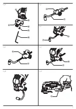
2.  Adjust the length of the guide by pulling out or pushing 

inward to achieve the desired length as shown in Figure L.

3.  Secure the guide in place by turning the depth/cut 

adjustment knob 

 14 

 clockwise. To release the guide turn 

the depth/cut adjustment knob counterclockwise.

nOTE:

 The guide arm can also be placed in the guard assembly 

vertically in order to set the height off a cut. Refer to Figure M.

Attaching the Dust Extraction Adaptor (Fig. Q)

The Dust Extraction Adaptor allows you to connect the tool to 
an external dust extractor, either using the AirLock™ system 
(DWV9000‑XJ), or a standard 35 mm dust extractor fitment.

1.  Attach the dust extraction adaptor 

 17 

 by inserting the 

tabs 

 13 

 in to the accessory side mount slots 

 5 

nOTE: 

The dust extraction adaptor can be attached to either 

side of the tool.

2.  Insert screw 

 15 

 and washer 

 21 

 into the dust extraction 

adaptor 

 17 

 and tighten with the supplied hex wrench 

 16 

.

nOTE:

 The tool will automatically shut off after operating 

for five minutes with the lock‑on button engaged. To restart 
the tool, the user will have to release the trigger and repress 
lock‑on button.

Speed Selector (Fig. A) 

DCS356

Your tool is equipped with a speed selector 

 10 

 which allows 

you to select one of the three speeds that limits the full speed. 
Select the speed based on the application and control the speed 
of the tool using the variable speed trigger switch 

 1 

.

LED Worklight (Fig. P)

The LED worklight 

 2 

 will activate when the trigger is depressed. 

It will automatically shut off following a short period of time 
once the trigger is released.

Using the Dust Extraction Adaptor with the 

Sanding Platen (Fig. R)

1.  Attach the dust extraction adaptor 

 17 

. Refer to

 Attaching 

the Dust Extraction Adaptor

.

2.  Attach the sanding platen 

 23 

 as described under 

Installing/Removing Accessories

.

3.  Attach sanding sheet as described under 

Installing/

Removing Sanding Sheets

.

Using the Dust Extraction Adaptor with 

Plunge Cutting Accessory (Fig. S)

1.  Attach the dust extraction adaptor. Refer to

 Attaching the 

Dust Extraction Adaptor

.

2.  Push dust extraction arm 

 19 

 into the lower aperture of the 

dust extraction adaptor 

 17 

.

3.  Attach plunge cutting blade as described under 

Installing/

Removing Accessories

.

4.  Adjust the dust extraction arm 

 19 

 for best results.

Helpful Hints

•  Always ensure the workpiece is firmly held or clamped to 

prevent movement. Any movement of the material may 
affect the quality of the cutting or sanding finish.

•  Do not start sanding without having the sandpaper 

attached to sanding platen.

•  Use coarse grit paper to sand rough surfaces, medium grit 

for smooth surfaces and fine grit for the finishing surfaces. If 
necessary, first make a test run on scrap material.

•  Excessive force will reduce the working efficiency and cause 

motor overload. Replacing the accessory regularly will 
maintain optimum working efficiency.

•  Do not allow the sandpaper to wear away, it will damage 

the sanding pad.

•  If the tool overheats, especially when used at low speed, 

set the speed to maximum and run it with no load for 2–3 
minutes to cool the motor. Avoid prolonged usage at very 
low speeds. Always keep the blade sharp.

Summary of Contents for DCS356N

Page 1: ...DCS355 DCS356 ...

Page 2: ...B Copyright DeWALT English original instructions 5 ...

Page 3: ...1 Fig A Fig B 4 1 3 2 10 DCS356 DCS355 6 7 9 8 11 5 8 9 9 8 XXXX XX XX 25 ...

Page 4: ...2 Fig C Fig D Fig E Fig F Fig G 3 22 24 23 16 18 12 20 ...

Page 5: ...3 Fig H Fig I Fig J Fig K Fig L Fig M Fig N 14 7 1 14 7 7 6 6 7 16 15 21 13 5 6 ...

Page 6: ...4 Fig O Fig P Fig R Fig S Fig Q 2 4 1 13 17 15 16 5 21 17 23 17 19 ...

Page 7: ... Li Ion Li Ion Oscillating frequency min 1 0 20000 0 20000 Oscillating angle 1 6 1 6 Speed 1 min 1 15000 Speed 2 min 1 17000 Speed 3 min 1 20000 Weight without battery pack kg 1 1 1 1 Noise values and or vibration values triax vector sum according to EN62841 2 4 LPA emission sound pressure level dB A 86 86 LWA sound power level dB A 97 97 K uncertainty for the given sound level dB A 3 3 Vibration ...

Page 8: ...40 350 300 180 150 80 120 180 X DCB549 18 54 15 0 5 0 2 12 125 730 450 380 230 170 90 125 230 X DCB181 18 1 5 0 35 22 70 45 35 22 22 22 22 22 45 DCB182 18 4 0 0 61 60 40 185 120 100 60 60 45 60 40 60 40 60 120 DCB183 B G 18 2 0 0 40 30 90 60 50 30 30 30 30 30 60 DCB184 B G 18 5 0 0 62 75 50 240 150 120 75 75 60 75 50 75 50 75 150 DCB185 18 1 3 0 35 22 60 40 30 22 22 22 22 22 40 DCB187 18 3 0 0 54 ...

Page 9: ...overreach Keep proper footing and balance at all times This enables better control of the power tool in unexpected situations f Dress properly Do not wear loose clothing or jewellery Keep your hair and clothing away from moving parts Loose clothes jewellery or long hair can be caught in moving parts g If devices are provided for the connection of dust extraction and collection facilities ensure th...

Page 10: ...ion Risk of personal injury due to prolonged use SAVE THESE INSTRUCTIONS b Use power tools only with specifically designated battery packs Use of any other battery packs may create a risk of injury and fire c When battery pack is not in use keep it away from other metal objects like paper clips coins keys nails screws or other small metal objects that can make a connection from one terminal to ano...

Page 11: ...Do not place any object on top of charger or place the charger on a soft surface that might block the ventilation slots and result in excessive internal heat Place the charger in a position away from any heat source The charger is ventilated through slots in the top and the bottom of the housing Do not operate charger with damaged cord or plug have them replaced immediately Do not operate charger ...

Page 12: ...r falling hazard Some tools with large battery packs will stand upright on the battery pack but may be easily knocked over Transportation WARNING Fire hazard Transporting batteries can possibly cause fire if the battery terminals inadvertently come in contact with conductive materials When transporting batteries make sure that the battery terminals are protected and well insulated from If the char...

Page 13: ...ct it will operate as an 18V battery When the FLEXVOLTTM battery is in a 54V or a 108V two 54V batteries product it will operate as a 54V battery Transport Mode When the cap is attached to the FLEXVOLTTM battery the battery is in Transport mode Keep the cap for shipping When in Transport mode strings of cells are electrically disconnected within the pack resulting in 3 batteries with a lower Watt ...

Page 14: ...2021 XX XX Year of Manufacture Markings on Tool The following pictograms are shown on the tool Read instruction manual before use Wear ear protection Package Contents The package contains 1 Adaptor for all blades 1 31 mm x 43 mm Fastcut wood blade 1 Sanding pad 1 31 mm x 43 mm Wood with nails blade 1 Rigid scraper blade 1 Blade adaptor and hex key 1 Dust extraction adaptor 1 Cutting guide 1 100 mm...

Page 15: ...ion WARNING Risk of lacerations or burns Do not touch the sharp edges of accessories at any time Do not touch workpiece or blade immediately after operating the tool They can become very hot Handle carefully Always allow accessories and workpiece to cool before handling 1 Attach the sanding platen 23 as described under Installing Removing Accessories 2 Align the edges on the sanding sheet with the...

Page 16: ...an be attached to either side of the tool 2 Insert screw 15 and washer 21 into the dust extraction adaptor 17 and tighten with the supplied hex wrench 16 NOTE The tool will automatically shut off after operating for five minutes with the lock on button engaged To restart the tool the user will have to release the trigger and repress lock on button Speed Selector Fig A DCS356 Your tool is equipped ...

Page 17: ...ies other than those offered by DeWALT have not been tested with this product use of such accessories with this tool could be hazardous To reduce the risk of injury only DeWALT recommended accessories should be used with this product Consult your dealer for further information on the appropriate accessories Cleaning WARNING Blow dirt and dust out of the main housing with dry air as often as dirt i...

Page 18: ......

Page 19: ......
Page 20: ...014353 39 039 9590200 Fax 39 039 9590311 www dewalt it Nederlands DeWALT Netherlands BVPostbus 83 6120 AB BORN Tel 31 164 283 063 Fax 31 164 283 200 www dewalt nl Norge DeWALT Postboks 4613 0405 Oslo Norge Tel 45 25 13 00 Fax 45 25 08 00 www dewalt no kundeservice no sbdinc com Österreich DeWALT Werkzeug Vertriebsges m b H Oberlaaerstrasse 248 A 1230 Wien Tel 01 66116 0 Fax 01 66116 614 www dewalt...

Reviews: