background image

English

11

for the manufacturer's label to see if they can be used for 
surface grinding or only edge grinding/cutting. A Type 1/41 
guard must be used for any wheel where surface grinding 
is forbidden. Cutting can also be performed by using a 
Type 1/41 wheel and a Type 1/41 guard.

nOTE:

 See the 

Accessories Chart

 to select the proper guard 

/ accessory combination.

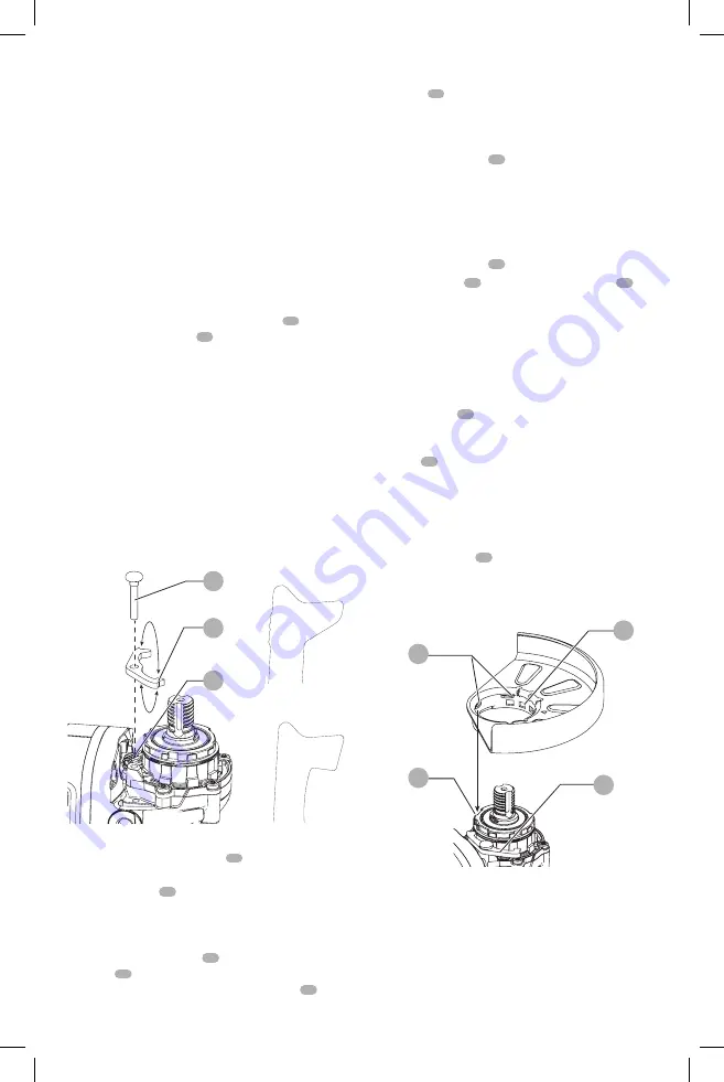
Adjusting and Mounting Guard (Fig. F, G)


CAUTION:

 Turn unit off and unplug the tool before 

making any adjustments or removing or installing 
attachments or accessories.


CAUTION:

 BEFORE operating the tool, identify which 

guard adjustment option your tool is set to. 

Adjustment Options

For guard adjustment, the guard release lever 

 10 

 engages 

one of the alignment holes 

 17 

 on the guard collar using a 

ratcheting feature. Your grinder offers two options for this 
adjustment.
• 

One-touch

TM

In this position the engaging face 

is slanted and will ride over to the next alignment 
hole when guard is rotated in a clockwise direction 
(spindle facing user) but self-locks in the counter-
clockwise direction.

• 

Two-touch

TM

:

 In this position the engaging face is 

straight and squared off. It will NOT ride over to the next 
alignment hole unless guard release lever is pressed and 
held while simultaneously rotating the guard in either 
a clockwise or counter-clockwise direction (spindle 
facing user). 

One Touch

Two Touch

Fig. F

14

10

13

setting guard Adjustment Options

To adjust the guard release lever 

 10 

 for desired 

adjustment option:

1.  Remove screw 

 14 

 using a T20 bit.

2.  Remove the guard release lever taking note of the 

spring position. Choose the end of the lever for the 
desired adjustment option. One-touch will use the 
slanted end of the lever 

 10 

 to engage the alignment 

holes 

 17 

 on the guard collar. Two-touch will use the 

squared end to engage the alignmnet holes 

 17 

 on the 

guard collar.

3.  Replace the lever, positioning the chosen end under the 

spring 

 13 

. Ensure the lever is in proper contact with 

the spring.

4.  Replace screw and torque to 2.0-3.0N-m. Ensure proper 

installation with spring return function by depressing 
guard release lever 

 10 

.

Mounting guard (Fig. g)


CAUTION:

 Prior to mounting guard, ensure the screw, 

lever, and spring are fitted correctly before mounting 
the guard.

1.  With the spindle facing the operator, press and hold the 

guard release lever 

 10 

.

2.  Align the lugs 

 15 

 on the guard with the slots 

 16 

 on 

the gear case.

3.  Push the guard down until the guard lugs engage and 

rotate them in the groove on the gear case hub. Release 
the guard release lever.

4.  To position the guard: 

One-touch

TM

Rotate the guard clockwise into the 

desired working position. Press and hold the guard 
release lever 

 10 

release lever to rotate the guard in the 

anti-clockwise direction. 

Two-touch

TM

:

 Press and hold the guard release 

lever 

 10 

. Rotate the guard clockwise or anti-clockwise 

into the desired working position.  

nOTE: 

The guard body should be positioned between 

the spindle and the operator to provide maximum 
operator protection. 
The guard release lever should snap into one of the 
alignment holes 

 17 

 on the guard collar. This ensures 

that the guard is secure.

5.  To remove the guard, follow steps 1–3 of these 

instructions in reverse.

Fig. G

17

16

15

10

Flanges and Wheels


WARNING: To reduce the risk of serious personal 
injury, turn unit off and remove the battery pack 
before making any adjustments or removing/
installing attachments or accessories.

 An 

accidental start-up can cause injury.

Summary of Contents for DCG414B

Page 1: ... word Indicates a safety related message NOTICE Indicates a practice not related to personal injury which if not avoided may result in property damage Fig A WARNING Read all safety warnings and all instructions Failure to follow the warnings and instructions may result in electric shock fire and or serious injury WARNING To reduce the risk of injury read the instruction manual If you have any ques...

Page 2: ...t such as dust mask non skid safety shoes hard hat or hearing protection used for appropriate conditions will reduce personal injuries c Prevent unintentional starting Ensure the switch is in the off position before connecting to power source and or battery pack picking up or carrying the tool Carrying power tools with your finger on the switch or energizing power tools that have the switch on inv...

Page 3: ...ty rating of your power tool Incorrectly sized accessories cannot be adequately guarded or controlled f Threaded mounting of accessories must match the grinder spindle thread For accessories mounted by flanges the arbor hole of the accessory must fit the locating diameter of the flange Accessories that do not match the mounting hardware of the power tool will run out of balance vibrate excessively...

Page 4: ...is entering into the pinch point can dig into the surface of the material causing the wheel to climb out or kick out The wheel may either jump toward or away from the operator depending on direction of the wheel s movement at the point of pinching Abrasive wheels may also break under these conditions Kickback is the result of tool misuse and or incorrect operating procedures or conditions and can ...

Page 5: ...ot overstress the wires by applying excessive load to the brush The wire bristles can easily penetrate light clothing and or skin b If the use of a guard is recommended for wire brushing do not allow any interference of the wire wheel or brush with the guard Wire wheel or brush may expand in diameter due to work and centrifugal forces c Safety goggles or safety glasses with side shields and a full...

Page 6: ...cations where the temperature may reach or exceed 104 F 40 C such as outside sheds or metal buildings in summer For best life store battery packs in a cool dry location NOTE Do not store the battery packs in a tool with the trigger switch locked on Never tape the trigger switch in the ON position Do not incinerate the battery pack even if it is severely damaged or is completely worn out The batter...

Page 7: ...uel gauge will not illuminate and the battery will need to be recharged Fig B 21 NOTE The fuel gauge is only an indication of the charge left on the battery pack It does not indicate tool functionality and is subject to variation based on product components temperature and end user application For more information regarding fuel gauge battery packs please contact call 1 800 4 DeWALT 1 800 433 9258...

Page 8: ... an authorized service center Do not disassemble the charger take it to an authorized service center when service or repair is required Incorrect reassembly may result in a risk of electric shock electrocution or fire Disconnect the charger from the outlet before attempting any cleaning This will reduce the risk of electric shock Removing the battery pack will not reduce this risk NEVER attempt to...

Page 9: ...rk surface If wall mounting locate the charger within reach of an electrical outlet and away from a corner or other obstructions which may impede air flow Use the back of the charger as a template for the location of the mounting screws on the wall Mount the charger securely using drywall screws purchased separately at least 1 25 4 mm long with a screw head diameter of 0 28 0 35 7 9 mm screwed int...

Page 10: ...cycled turned on and off to restart tool The tool will power off each time the current load reaches the overload current value motor burn up point If continued overload shutdowns occur apply less force weight on the tool until the tool will function without the overload engaging Electronic Soft Start This feature limits the initial start up speed allowing the tool to build up to full speed gradual...

Page 11: ...desired adjustment option One touch will use the slanted end of the lever 10 to engage the alignment holes 17 on the guard collar Two touch will use the squared end to engage the alignmnet holes 17 on the guard collar 3 Replace the lever positioning the chosen end under the spring 13 Ensure the lever is in proper contact with the spring 4 Replace screw and torque to 2 0 3 0N m Ensure proper instal...

Page 12: ...ing Sanding Backing Pads Fig A I NOTE Use of a guard with sanding discs that use backing pads often called fiber resin discs is not required Since a guard is not required for these accessories the guard may or may not fit correctly if used WARNING Failure to properly seat the flange clamp nut wheel could result in serious injury or damage to the tool or wheel WARNING Proper guard must be reinstall...

Page 13: ...the charger as described in the charger section of this manual Fig K 11 12 Proper Hand Position Fig L WARNING Toreducetheriskofseriouspersonalinjury ALWAYS useproperhandpositionasshown WARNING Toreducetheriskofseriouspersonal injury ALWAYS holdsecurelyinanticipationofa suddenreaction Proper hand position requires one hand on the main handle and one hand on the side handle Fig L Trigger Switch and ...

Page 14: ...rk area The filter should be replaced daily or whenever the wearer has difficulty breathing NOTE Only those dust masks suitable for working with lead paint dust and fumes should be used Ordinary painting masks do not offer this protection See your local hardware dealer for the proper N I O S H approved mask 3 NO EATING DRINKING or SMOKING should be done in the work area to prevent ingesting contam...

Page 15: ...ust have a 7 8 22 2 mm arbor hole If it does not it may have been designed for a circular saw Use only the accessories shown in the Accessories Chart of this manual Accessory ratings must always be above tool speed as shown on tool nameplate WARNING Handle and store all abrasive wheels carefully to prevent damage from thermal shock heat mechanical damage etc Store in a dry protected area free from...

Page 16: ...y pack is tampered with in any way DeWALT is not responsible for any injury caused by tampering and may prosecute warranty fraud to the fullest extent permitted by law 90 DAY MONEY BACK GUARANTEE If you are not completely satisfied with the performance of your DeWALT Power Tool Laser or Nailer for any reason you can return it within 90 days from the date of purchase with a receipt for a full refun...

Reviews: