2
equipment off and on, the user is encouraged to try to correct the interference by one
or more of the following measures:
•
Reorient or relocate the receiving antenna.
•
Increase the separation between the equipment and the receiver.
•
Connect the equipment into an outlet on a circuit different from that to
which the receiver is connected
•
Consult the dealer or an experienced radio/TV technician for help.
NOTICE
: Per FCC Part 15, changes or modifications to this equipment not expressly
approved by D
E
WALT could void your authority to operate this equipment.
WARNING:
To reduce the risk of fire or electric shock, do not expose this
apparatus to rain or moisture.
Use only in dry locations
.
CAUTION:
To prevent electric shock, ensure mains supply is earthed and only a 3
pin plug is used .
Electrical Safety
The electric motor has been designed for one voltage only. Always check that the
power supply corresponds to the voltage on the rating plate. 240 V AC means your
tool will operate on alternating current. As little as 10% lower voltage can cause loss
of power and can result in overheating. All D
E
WALT tools are factory tested; if this
tool does not operate, check the power supply. Your D
E
WALT tool is double insulated,
therefore no earth wire is required.
•
Young children and the infirm.
This appliance is not intended for use by
young children or infirm persons without supervision. Young children should be
supervised to ensure that they do not play with this appliance.
•
Replacement of the supply cord.
If the supply cord is damaged, it must be
replaced by the manufacturer or an authorised D
E
WALT Service Centre in order
to avoid a hazard.
Extension Cords
CAUTION:
Use only extension cords that are approved by the country’s Electrical
Authority. Before using extension cords, inspect them for loose or exposed wires,
damaged insulation and defective fittings. Replace the cord if necessary.
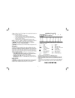
MINIMUM GAUGE FOR CORD SETS
For Cable length (m):
7.5 15 25 30 45 60
Use Cable with minimum rating (Amperes)
Tool Amperes
0 - 3.4
7.5
7.5
7.5
7.5
7.5
7.5
3.5
-
5.0 7.5 7.5 7.5 7.5 10 15
5.1 - 7.0
10
10
10
10
15
15
7.1 - 12.0
15
15
15
15
20
20
12.1 - 20.0
20
20
20
20
25
–
• The label on your tool may include the following symbols. The symbols and their
definitions are as follows:
V ..................volts
A .............amperes
Hz ................hertz
W ............watts
min ..............minutes
.........alternating current
.........direct current
.........alternating or direct current
...............Class I Construction
no ...........no load speed
....................
(grounded)
...........earthing terminal
...............Class II Construction
..........safety alert symbol
....................
(double insulated)
BPM ........beats per minute
…/min ...........per minute
RPM ........revolutions per minute
................shock hazard symbol
Important Safety Instructions for All Battery Packs
When ordering replacement battery packs, be sure to include catalog number and
voltage. Consult the chart at the end of this manual for compatibility of chargers and
battery packs.
The battery pack is not fully charged out of the carton. Before using the battery pack
and charger, read the safety instructions below. Then follow charging procedures
outlined.
READ ALL INSTRUCTIONS
Summary of Contents for DC013-XE
Page 1: ...DC013 XE HEAVY DUTY WORK SITE CHARGER RADIO INSTRUCTION MANUAL ...
Page 2: ......
Page 14: ...12 ...
Page 15: ...13 ...


