


8
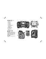
COMPONENTS (FIG. 1, 2)
A. Power/Volume control
B. Tuning dial
C. Arrow buttons
D. Mode button
E. Clock button
F. Memory buttons
G. LCD display
H. Battery compartment latch
I. Charging receptacle
J. Charging light
K. Auxiliary port
L. USB Power outlet port
M. Coin cell battery door
N. Coin cell battery
O. Outlets
P. Battery door screw
OPERATING THE RADIO
(FIG. 1, 2)
Your charger/radio is equipped with memory
capacity in order to store the time and your
selected memory channels. When the radio
is in the off position, this memory capacity
is powered by one coin cell battery that is
included with the charger/radio.
AC Operation
Unwrap power cord and plug into 230 V AC
wall outlet.
FIG 1
B
A
J
K
G
E
C
D
F
F
K
J
O
FIG 2
H
M
P
I
N
L
L
Summary of Contents for DC013-XE
Page 1: ...DC013 XE HEAVY DUTY WORK SITE CHARGER RADIO INSTRUCTION MANUAL ...
Page 2: ......
Page 14: ...12 ...
Page 15: ...13 ...