


7
English
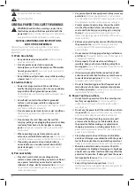
Proper hand position requires one hand on the mounted side
handle
2
, with the other hand on the main handle
5
.
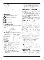
Mode Selection (Fig. E)
WARNING:
Do not select the operating mode when the
tool is running. Tool must come to a complete stop before
activating the mode selector button or damage to the tool
may result.
Your tool is equipped with a mode selector dial
4
to select the
mode appropriate to desired operation.
symbol
Mode
Application
Bit
Adjustment
Chisel bit position adjustment
hammering/
Chipping
Light chipping, chiseling
and demolition
To Select a Mode
• Rotate the mode selector dial so that the arrow points to the
symbol corresponding for the desired mode.
nOTE:
The arrow on the mode selector dial
4
must be pointing
at a mode symbol at all times. There are no operable positions
in between.
Indexing the Chisel Position (Fig. E)
The chisel can be indexed and locked into 24 different positions.
1. Rotate the mode selector switch
4
until it points towards
the
position.
2. Rotate the chisel in the desired position.
3. Set the mode selector switch
4
to the “Hammering/
Chipping” position.
4. Twist the chisel until it locks in position.
Performing an Application (Fig. A, E)
WARNING: TO REDUCE THE RISK OF PERSONAL
INJURY, ALWAYS
ensure workpiece is anchored or
clamped firmly.
nOTE:
Operating temperature of this tool is 7 to +40 ˚C. Using
the tool outside of this temperature range will decrease the life
of the tool.
1. Insert the appropriate chisel and rotate it by hand to lock it
into the desired position. Refer to
Bit and Bit Holder
.
2. Using the mode selector dial
4
, select chipping mode.
Refer
to
Mode Selection
.
3. Adjust the side handle
2
as necessary. Refer to
Mounting
the Side Handle Assembly
.
4. Place the chisel on the desired location.
5. Depress the ON/OFF rocker switch
1
.
6. To stop the hammer, release the ON/OFF rocker switch.
Proper Hand Position (Fig. D)
WARNING:
To reduce the risk of serious personal injury,
ALWAYS
use proper hand position as shown.
WARNING:
To reduce the risk of serious personal
injury,
ALWAYS
hold securely in anticipation of a
sudden reaction.
OPERATION
Instructions for Use
WARNING:
Always observe the safety instructions and
applicable regulations.
WARNING:
To reduce the risk of serious personal
injury, turn tool off and disconnect tool from power
source before making any adjustments or removing/
installing attachments or accessories.
An accidental
start-up can cause injury.
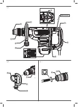
The side handle
2
clamps to the front of the gear case and may
be rotated 360˚ to permit right- or left-hand use.
Mounting the Side Handle
Assembly
(Fig. B)
1. Widen the ring opening
12
of the side handle
2
by rotating the screw for side handle mounting
10
anti-clockwise.
2. Slide the assembly onto the nose of the tool, through the
steel ring
12
and onto the collar
3
, past the chisel holder
and sleeve.
3. Rotate the side handle assembly to the desired position.
4. Lock the side handle mounting assembly in place by
securely tightening the screw for side handle mounting
10
rotating it clockwise so that the assembly will not rotate.
Bit and Bit Holder
WARNING:
Burn Hazard.
ALWAYS
wear gloves when
changing bits. Accessible metal parts on the tool and bits
may get extremely hot during operation. Small bits of
broken material may damage bare hands.
WARNING:
Do not attempt to tighten or loosen chisel bits
(or any other accessory) by gripping the front part of the
chuck and turning the tool on. Damage to the chuck and
personal injury may occur.
The chipping hammer can be fitted with various chisel bits
depending on the desired application.
Use sharp bits only.
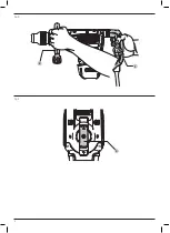
Inserting and Removing SDS MAX Bits (Fig. C)
nOTE:
Accessories and attachments used must be lubricated
around the SDS fitment before installation.
1. Pull back the locking sleeve
7
and insert the bit shank. The
bit shank must be clean.
2. Turn the bit slightly until the sleeve snaps back into position.
3. Ensure the bit is properly engaged.
nOTE:
The bit needs to move several centimeters in and out
of the tool holder
6
when properly engaged.
4. To remove the bit, pull back the locking sleeve and pull the
bit out.
Bit Position Adjustment
Turn the mode selector to bit adjustment icon (Refer to
Mode
Selection
) to adjust the chisel to the desired position. There are
multiple positions to set the angle of the chisel.
nOTE:
After finding the desired position, slightly maneuver
the chisel bit back and forth to ensure the chisel is
properly engaged.
Summary of Contents for D25892
Page 1: ...D25892 ...
Page 3: ...1 Fig A Fig B Fig C 3 2 6 7 12 10 1 5 2 3 4 6 7 8 XXXX XX XX 11 10 9 ...
Page 4: ...2 Fig E Fig D 2 5 4 ...
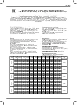
Page 27: ...25 Türkçe KULLANMA A98 8 ødø1 ø ø 5 Matkaplar 7 yıl a Sözleşmeden dönme ...
Page 35: ......
Page 36: ...N754650 11 19 ...