31
E
N
G
15)
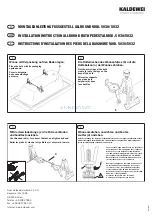
Position the plugs supplied
(H: either white or black, as
preferred) to cover the holes
where the self-tapping screws
were inserted.
16)
At this point, the brace
rod (M) needs to be positioned
between the wall and the upper
column of the fixed door.
17)
Using a pencil, mark out
the two points where the rod
will be positioned, on the wall
and column.
18)
Drill a hole into the wall
using the wall bit (point A) and
into the upper column of the
fixed side (point B) using the
iron bit.
A
B
Summary of Contents for Savoy K
Page 3: ...2 PACKING LIST struttura porta doccia A C B A...
Page 19: ...18 29 Al termine la porta doccia dovrebbe apparire come mostrato in figura...
Page 21: ...20 PACKING LIST shower enclosure structure A C B A...
Page 37: ...36 29 At the end the shower enclosure should look the same as in the illustration...
Page 39: ...38 PACKING LIST AUFBAU DUSCHT R A C B A...
Page 55: ...54 29 Am Ende sollte die Duscht r so aussehen wie sie in der Abbildung dargestellt ist...
Page 57: ...56 LISTE DES ACCESSOIRES structure porte de douche A C B A...
Page 73: ...72 29 A la fin des op rations la porte de douche devrait appara tre comme la figure le montre...
Page 75: ...74 LISTA DE CONTENIDO estructura de la puerta de la ducha A C B A...
Page 91: ...90 29 Al final la puerta de la ducha debe presentar el aspecto mostrado en la imagen...
Page 93: ...92 A B B...
Page 94: ...93 P Y C A x2 B C D x5 E x5 F x5 G x9 H x9 x9 I L M N S D E L F G H I M N E D F G H...
Page 95: ...94 1...
Page 96: ...95 P Y C 2 B...
Page 97: ...96 3 B C 4...
Page 98: ...97 P Y C 5...
Page 99: ...98 6...
Page 100: ...99 P Y C 7 8 9 D...
Page 101: ...100 10 B C D 11...
Page 102: ...101 P Y C 12 1 2 3 4 1 2 4 3...
Page 103: ...102 13 E 2 5 1 2 3 4 12 14 A B A B...
Page 104: ...103 P Y C 15 16 M 17 18 A B...
Page 105: ...104 19 22 S N 21 F G H 20...
Page 106: ...105 P Y C 25 26 24 L 23 L...
Page 107: ...106 27...
Page 108: ...107 P Y C 28...
Page 109: ...108 29...


