background image

18

Appendix 2

Guidance and Manufacturer’s Declaration - Electromagnetic Immunity

The


model extriCARE™ 2400


is intended for use in the electromagnetic environment 

specified below. The customer or the user of the 

model extriCARE™ 2400

 should 

assure that it is used in such an environment.

   Immunity Test             IEC 60601 Test Level             Compliance Level         Electromagnetic Environment  


           Guidance  

Electrostatic 

discharge (ESD)

IEC 61000-4-2

Electrical fast 

transient/burst

IEC 61000-4-4

Surge

IEC 61000-4-5

Voltage dips, 

short 

interruptions 

and voltage 

variations on 

power supply 

input lines

IEC 61000-4-11

Power 

frequency 

(50/60 Hz) 

magnetic field

IEC 61000-4-8

6 kV contact

8 kV air

2 kV for power 

supply lines

1 kV line(s) and 

neutral

<5% UT (>95% 

dip in UT) for 

0.5 cycle

40% UT (60% 

dip in UT) for 

5 cycles 

70% UT (30% 

dip in UT) for 

25 cycles

<5% UT (>95% 

dip in UT) for 5s

3 A/m

6 kV contact

8 kV air

2 kV for power 

supply lines

1 kV line(s) and 

neutral

<5% UT (>95% 

dip in UT) for 0.5 

cycle

40% UT (60% 

dip in UT) for 5 

cycles 

70% UT (30% 

dip in UT) for 25 

cycles

<5% UT (>95% 

dip in UT) for 5s

Not applicable

Floors should be wood,  

concrete or ceramic tile. If 

floors are covered with  

synthetic material, the  

relative humidity should be 

at least 30 %. 

Mains power quality should 

be that of a typical 

commercial or hospital 

environment. 

Mains power quality should 

be that of a typical  

commercial or hospital 

environment. 

Mains power quality should 

be that of a typical 

commercial or hospital 

environment. If a dip or an 

interruption of mains power 

occurs, the current of the 

model extriCARE™ 2400

 may 

be dropped off from normal 

level, it may be necessary to 

use uninterruptible power 

supply or a battery.

Not applicable

NOTE: UT is the a.c. mains voltage prior to application if the test level.


Summary of Contents for extriCARE 2400

Page 1: ...www devonmedicalproducts com 866 446 0092 Negative Pressure Wound Therapy System extriCARE 2400 Operating Manual IFU30 0003 Rev A 20121024...

Page 2: ...onment in either intermittent or continuous mode This allows the user to program the specific pressure ranging from 40mmHg to 140mmHg In continuous mode the pressure is applied to the wound as long as...

Page 3: ...or use Single Use Only Date Of Manufacture Type B Applied Part Internally powered electrical device Keep Dry Serial Number Prescription Use Only Power Switch Manufacture Lot Number Biohazard 2 SN LOT...

Page 4: ...0 240 V 50 60 Hz 0 4A Output 5V 1 5A VACUUM MODES Continuous or Intermittent OPERATING CONDITIONS Temperature 5 C to 40 C 41 F to 104 F Humidity 15 to 85 non condensing PRESSURE OPTIONS 40mmHg 140mmHg...

Page 5: ...ubing set EC2400 SO extriCARE NPWT Dressing Small oval with tubing set EC2400 S extriCARE NPWT Dressing Sacrum with tubing set EC2400 IM extriCARE NPWT Dressing Incision Management with tubing set EC2...

Page 6: ...must be applied more frequently than the dressing change schedule allows 7 Warnings Review this manual prior to using the extriCARE 2400 Negative Pressure Wound Therapy Pump System If clarification is...

Page 7: ...e factored into the therapy prescription as the attending clinician sees fit 3 ENVIRONMENT a Defibrillation Remove the extriCARE dressing if defibrillation is required in the area of dressing placemen...

Page 8: ...sympathetic nervous system stimulation discontinue extriCARE therapy to minimize sensory stimulation and give immediate medical assistance 7 MODE In unstable anatomical structures continuous rather th...

Page 9: ...ed 8 4 Dressing Management The extriCARE dressing is a one piece all inclusive dressing and should be removed in one piece In the event that the dressing comes apart all dressing materials must be rem...

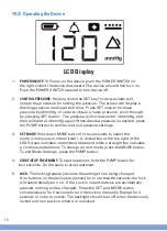
Page 10: ...he canister to the NPWT device 5 MODE SYMBOL Indicates pump operating mode continuous or intermittent 6 MODE BUTTON Allows user to set the pump to either continuous or intermittent mode 7 POWER PLUG E...

Page 11: ...iCARETM System being used with an adapter that is not recommended There is a risk of volt age incompatibility if the input voltage is greater than 6V Less than 25 power remaining indicating that extri...

Page 12: ...flashing on LCD screen Yellow LED flashing every 2 seconds Alarm symbol and 000 flashing on LCD screen Yellow LED flashing every 2 seconds Alarm symbol flashing on LCD screen Yellow LED flashing ever...

Page 13: ...sing The dressing should be protected from moisture during bathing or changed prior to reconnecting to the pump Do not use the extriCARE 2400 Negative Pressure Wound Therapy Pump while show ering or b...

Page 14: ...ft dressing material may be applied between each toe When used on the foot aggressive measures should be taken to protect the foot and divert unnecessary pressure If the dressing is applied over a new...

Page 15: ...MODE Hold down MODE button for two seconds to select the mode continuous or intermittent A dotted line at the top right of the LCD Screen indicates intermittent treatment while a straight line indica...

Page 16: ...ce will void the warranty In the event the extriCARE device requires repairs it should be returned to the medical equipment company or to Devon Medical Products directly Power adapter The extriCARE de...

Page 17: ...en damaged in transit or has been subject to misuse neglect or accident or has been used in violation of Devon Medical Products instructions including without limitation the instructions contained in...

Page 18: ...io frequency transmitting equipment and other sources of electrical noise in a healthcare environ ment high levels of interference may induce an abnormal stoppage or other disruption of this device Th...

Page 19: ...for 5 cycles 70 UT 30 dip in UT for 25 cycles 5 UT 95 dip in UT for 5s 3 A m 6 kV contact 8 kV air 2 kV for power supply lines 1 kV line s and neutral 5 UT 95 dip in UT for 0 5 cycle 40 UT 60 dip in U...

Page 20: ...higher the frequency range applies NOTE 2 These guidelines may not apply in all situations Electromagnetic propagation is affected by absorption and reflection from structures objects and people a Fie...

Page 21: ...ance according to frequency of transmitter m output power of transmitter W 0 01 0 1 1 10 100 150 kHz to 80 MHz d 1 2 P 0 12 0 38 1 2 3 8 12 80 MHz to 800 MHz d 1 2 P 0 12 0 38 1 2 3 8 12 800 MHz to 2...

Page 22: ...50 69 Borquist O Ingemansson R et al Individualizing the Use of Negative Pre sure Wound Therapy for Optimal Wound Healing A focused Review of the Literature Ostomy Wound Management 2011 57 4 44 54 De...

Page 23: ...Guidelines for Managing Pressure Ulcers with Negative Pressure Wound Therapy Advances in Skin and Wound Care 2004 17 1 16 Kirby M Negative Pressure Wound Therapy British Journal of Diabetes Vascular D...

Page 24: ...www devonmedicalproducts com 866 446 0092...

Reviews: