Devatec ELECTROVAP RTH-LC User Manual Download Page 36

                                                                                         36                  

Pictures for illustra tive  purpos es 


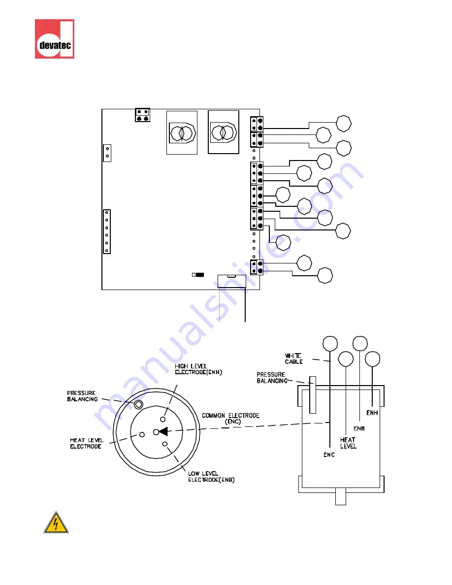
WATER LEVEL MANAGEMENT BOARD


50

45

51

52

WATER LEVEL 

SENSOR

X1

Devatec 
Ref: 500851/02

78

77

76

75

73
74

CO1

X51

68

70

X3

X2

69

67

22

56

62

64

63

64

63

25

61

59
60

58

57

23

24

50

21

55

53
54

52

50
51

51

52

47

44
45
46

42

43

45

E

LECTRO

V

AP

 RTH-LC 


Wiring diagrams


ALL WORKS CONCERNED WITH THE ELECTRICAL INSTALLATION MUST BE CARRIED OUT BY SKILLED AND QUALIFIED PERSONNEL. 

Summary of Contents for ELECTROVAP RTH-LC

Page 1: ...Pictures for illustrative purposes only R User manual Resistive steam humidifier from 3 to 17 kg h ...

Page 2: ...istance 14 Steam pipe positioning 15 18 Steam pipe installation 19 Room ventilation pack 20 Electrical installation Electrical tables 22 24 Electrical w iring 25 26 Control connection 27 Connecting options 28 29 RTH LC w iring schemes 30 36 Setting up 37 Software assistant User information menu 38 39 Humidifier status menu 40 Changing parameters menu 41 42 Alerts w arnings 43 47 Maintenance RTH LC...

Page 3: ...cted distrubances induced by radio frenquen cy fields EN 61000 4 4 Electrical fast transient burnt immunity test EN 61000 4 5 Surge immunity test EN 61000 4 2 Electrostatic discharge immunity test EN 60335 1 Low voltage safety of electrodomestical devices and similar EN 60335 2 88 Low voltage safety of electrodomestical devices and similar concerning humidifiers EN 60204 1 Safety of machinery Elec...

Page 4: ...faces and pipe w ork become very hot Ensure that equipment not sustaining high temperatures be kept aw ay Warning the end user should ensure that the equipment be disposed of according to the local prevailing regulations Delivery and storage Any loss or damage during delivery should be reported to carrier by registered letter within 3 working days and be advised to devatec or to authorized dealer ...

Page 5: ...ONLY intended for use with air handling systems or direct air humidifica tion ANY OTHER APPLICATION IS NOT CONSIDERED USE FOR THE INTENDED PURPOSE THE MANUFACTURER CANNOT BE MADE LIABLE FOR ANY DAMAGE RESULTING FROM INCORRECT USE Water ElectroVap RTH humidifiers are designed to be used with mains demineralized R O with a minimum conduc tivity of 30 µs or softened water On no account attempt to int...

Page 6: ...for illustrative purposes only 1 1 1 1 1 1 A B a C Ov erall dimensions mm Steam outlet mm Weight empty kg In operation kg A 550 1 140 a 140 25 35 B 680 C 272 Drain outlet mm RTH 3to15 ELECTROVAP RTH LC Dimensions ...

Page 7: ...e devatec steam humidifiers are designed to be installed on w all Make sure that the surface the humidifer is hanged on is strong enough Install the humidifier at the shortest distance of the steam pipe s a page 13 whenever possible for best performance Arrange position of the humidifier on w all to provide free access for easy maintenance see after installation draw ings here under Remove the blo...

Page 8: ...to the support D E TA ILA R4 R6 1 0 20 Installationprocedure Mark the 4 mounting holes and drill Insert pegs Screw the upper screws allow ing diam 6mm allow ing about 10 mm for hanging the cabinet Hang the cabinet and screw the low er screws Tighten up all the screws for securing the installation w hile ensuring that the cabinet is level Attachment point detail ...

Page 9: ... withstand any water spilling during servicing or if a problem occurs Information about the water quality chloride concentration 75mg l phosphate concentration 5mg l chlorine consentra tion 3 to 6 dA 100mg l poor concentration inCO2 organic elements in poor concentration The RTH humidifier can run with the following water qualities Tap or raw water water TH between 5 and 40 French grade Deminerali...

Page 10: ...r It is essential that a duplex softener be used A small volume of tap water must be added to the softener water to get a TH value of 10 minimum however a TH value of 12 is highly recommended A water analysis should be made to determine the sodium chloride content Far from what is generally considered the use of softened waters does not bring down the maintenance f re quency Only the use of revers...

Page 11: ...nderneath for the installation of the steam hose according to one of the shown examples the most suited to your installation A set of hose clamps is supplied for ensuring a correct installation The humidifier should be located within 3 m of the steam distribution pipe If the distance is superior to 3 m insulated steel or copper pipe of a slightly larger diameter must be used It should not exceed 6...

Page 12: ...r has its ow n drain pipe and tank arran gement in case a number of humidifiers is installed 4 Use w ater tanks w ith a lid that has w ater col lecting facilities option on request s a dra wing 1 5 A funnel can also be used s a pict 2 but it should be offset from the underside of the unit to prevent any steam and or condensa tion from getting into the cabinet The instal lation of a siphon as per t...

Page 13: ...pe for RTH LC 3 to 15 L mm D25 L290 290 D25 L590 590 D25 L790 790 D25 L1500 1500 D25 L1250 1250 D25 L1000 1000 Steamdistribution selection table Ø25mm Ø8mm ExpressPack L The Armstrong ExpressPack is a bespoke steam humidification system made to suit your configuration and ready to install in a ventilation duct It permits to have vapor trails absorbing distances as short as 600 mm For further refer...

Page 14: ...he attached calculation table can be used Nota bene this calculation table is to be used for temperatures betw een 20 C and 25 C HR1 relative humidity of air before humidification in HR2 relative humidity of air after humidification in Minimal humidification distance The steam distribution pipes must be positioned after the minimum humidification distance calculated w ith the help of the above tab...

Page 15: ...se contact devatec or their authorized agent for an alternative solution If accurate values cannot be reached a distance of 2 m should be considered as a minimum distance betw een pipes obstruction and 3 4 m before sensor or humidistat D D 5 x D 0 5 x D D 0 5 x D ELECTROVAP RTH LC Steam pipepositioning continued Before a junction before an air opening before a humidity Before after a constriction ...

Page 16: ... For further information please contact devatec or their authorized agent H1 110mm Minimum height betw een the duct floor and the axle of the steam pipe H2 140mm Minimum distance betw een two pipes H3 160mm Minimum height betw een the duct top and the axle of the steam pipe The H3 distance can be 80 mm at the shortest in case the steam pipe is installed at an angle of 30 The arrow shows the direct...

Page 17: ...is upw ard or downward the steam distribution pipe s must be tilted by 15 sidew ays 5 90 47 2 d 2 d In duct w ith limited height the distribution pipe s can be tilted by 30 to get the 80 mm minimum height D Humidification distance d Duct diameter continued ELECTROVAP RTH LC Steampipepositioning ...

Page 18: ...ifier RTH LC 3 to 15 ExpressPack duct insersion RTH LC 3 to 15 300 mm MINI 200 mm MINI Siphon must be full of water before starting up A loop hav ing the right diameter may also suit Conensates Draining system Condensates DRAIN DRAIN Condensats DRAIN continued ELECTROVAP RTH LC Steam pipe positioning ...

Page 19: ...ipe must be at levelwith the duct Threaded rod Rail Method 1 Method 2 ELECTROVAP RTH LC Steam pipe installation For ensuring the best steam distribution possible we would recommend to install the steam pipes as per the two methods described underneath How to installina duct Your steam pipes must be screwed onto the ventilation duct by the fixing plate with a set of 4 bolts and nuts of Ø5 mm For en...

Page 20: ...ere there is no ductworks The Blower Pack BP1 provides an output of 5kg h The direct steam connection to the humidifier is ensured by a Ø 25 mm steam hose The Blower Pack BP1 is energized by connecting it to terminals 3 4 of the humidif ier Allow a 3 m distance ahead to the BP1 for a free diffusion of the steam For use and installation of the Blower Pack ventilation unit please refer to the Blower...

Page 21: ... responsible for ensuring their suitability Please observe local regulations concerning the provision of electrical installations Check all electrical terminal screws at commissioning after 50 hours operation and at every service thereafter Take care the RTH LC electronic components are very sensitive to electrosta tic shocks Appropriate steps must be taken before any operation ELECTROVAP RTH LC E...

Page 22: ...19 13 1 3 4 3 230V RTH LC steamhumidifierin 3 x400V 50 60Hz RTH Steam production kg h Voltage V Nb of phase s Amperage A Power KW Nb of boiler s Nb of heating element s Power of heating element KW 8 6 230 3 13 5 1 3 1 9 230V RTH LC steamhumidifierin 3x208V 50 60Hz RTH Steam production kg h Voltage V Nb of phase s Amperage A Power KW Nb of boiler s Nb of heating element s Power of heating element K...

Page 23: ...g element s Power of heating element KW 5 3 6 415 3 6 4 1 3 1 9 277V 7 8 415 3 9 6 1 3 1 9 230V 15 19 415 3 20 14 1 3 4 3 230V 10 13 415 3 14 10 1 3 4 3 277V RTH LC steamhumidifierin 3x415V 50 60Hz RTH Steam production kg h Voltage V Nb of phase s Amperage A Power KW Nb of boiler s Nb of heating element s Power of heating element KW 15 16 460 3 15 12 1 3 4 3 277V 7 7 460 3 7 6 1 3 1 9 277V RTH LC ...

Page 24: ...g element s Power of heating element KW 7 8 480 3 7 6 1 3 1 9 277V 15 17 480 3 16 14 1 3 4 3 277V RTH LC steamhumidifierin 3x480V 50 60Hz RTH Steam production kg h Voltage V Nb of phase s Amperage A Power KW Nb of boiler s Nb of heating element s Power of heating element KW 7 7 575 3 5 5 1 3 1 9 346V 15 16 575 3 12 12 1 3 4 3 346V RTH LC steamhumidifierin 3x575V 50 60Hz RTH Steam production kg h V...

Page 25: ...nit 2 Power supply cable 3 Electrical compartment WARNING Failure to fit an electrical power isolator and MCB as part of the electrical installation signif icantly increases the risk of electric shock whichcan bef atal Q2 MCB and electrical power isolation The symbol between Q1 Q2 means that these MCB are coupled The power MCB Q2 and control MCB Q1 are mechanically linked together So if a fault is...

Page 26: ... of our optional transfomer preventing the installation of a specific neutral line ELECTROVAP RTH LC Wiring connection continued 1 2 3 4 15V 0V 15V 230V 400V J1 J2 J3 J4 42 42 41 41 39 39 40 40 Primary circuit protection External protection power Power 3x380 400VAC Transformer Prim 400V Sec 230V The neutral is not earthed In this case we advocate the installation of a transformer L2 L1 N L3 L PE R...

Page 27: ...l humidistat high level safety humidistat or to a ventilation system Outside connections 19 20 RTH PROPORTIONAL CONTROL X5 19 20 Hygrometer 1 2 3 4 0 _ 10 V S1 on 1 2 3 4 4 _ 20 mA S1 on 1 2 3 4 0 _ 20 V S1 on 1 2 3 4 1 _ 5 V S1 on 1 2 3 4 DEVATEC SENSOR S1 on 1 2 3 4 0 _ 5 V SENSOR V g Rh Devatec Sensor 1 2 connection control humidistat high level safety humidistat or and ventilation 1 2 1 2 1 2 ...

Page 28: ...s RS485 outlet MODBUSconnection RS485 Hardware connection The RS485 connection must be plugged on the J1 connector see pic Terminal 1 Data Terminal 2 Data Terminal 3 Signal Ground The S37 switch is use to enable or disable the line resistor In most of cases those resistors are useless and should be dis abled Speed of the communication 9600 Bauds sec changeable Packet size 8 bits Parity No parity S...

Page 29: ...Pictures for illustrative purposes REGISTER MAP ELECTROVAP RTH LC Connecting options RS485 outlet ALL WORKS CONCERNED WITH THE ELECTRICAL INSTALLATION MUST BE CARRIED OUT BYSKILLED AND QUALIFIED PERSONNEL ...

Page 30: ... X 1 6 7 8 9 10 X2 11 12 X3 13 14 X4 15 16 17 X6 2 1 22 23 2 4 25 X14 DEVA TEC Réf 5001 00 02 X 5 20 19 18 33 34 X21 53 54 X 22 6 0 61 6 2 X16 J1 3 J5 J3 F1 F4 J4 X23 35 34 P1 2 X8 0 1 X9 2 3 X 10 4 5 X11 28 29 2 1 31 32 X1 5 TI F2 F3 4 5 4 3 1 2 0 2 6 27 3 6 X 7 35 Switch ON OFF HUMIDIS 0 10 V 1 2 24 23 22 21 25 26 27 Blinda ge B OB IN E V A NN E D E V ID A NG E C AR TE P RIN C IPA LE PO R TE H U...

Page 31: ... 500600 0 3 X14 6 8 10 6 9 X1 2 X1 6 7 8 9 1 0 X2 11 12 X3 13 14 X4 15 16 17 X6 21 22 23 24 25 X1 4 DEVATEC Réf 50 0100 0 2 X5 20 19 18 33 34 X21 53 5 4 X22 60 6 1 62 X16 J1 3 J5 J3 F1 F4 J4 X23 35 34 P1 2 X8 0 1 X9 2 3 X10 4 5 X1 1 28 29 2 1 31 32 X15 TI F2 F3 4 5 4 3 1 2 0 2 6 27 3 6 X7 35 Switch ON OFF HUMIDIS 0 1 0V 1 2 24 23 22 21 25 26 27 Blindage BO B IN E V A N NE DE VI DA N G E C AR TE PR...

Page 32: ...LIFIED PERSONNEL RTH LC 3 5 STEAM HUMIDIFIERSin1 x230V ELECTROVAP RTH LC Wiring diagrams RTH R5 3 1 9KW 230V 5 4 3KW 230V Butée 4 A2 3 A1 2 T1 1 L1 Butée S1 COUVERCLE VUE DE DESSUS Façade appareil Front Unit 11 7 70 72 70 72 73 73 R8 11 7 Butée L2 L PE PE N L1 3 Butée 4 A1 A2 14NO A2 6T3 4T2 13NO 5L3 3L2 K1 2T1 1L1 Butée PE 2 1 ...

Page 33: ...HE ELECTRICAL INSTALLATION MUST BE CARRIED OUT BYSKILLED AND QUALIFIED PERSONNEL Butée 4 A2 3 A1 2 T1 1 L1 Butée S1 COUVERCLE VUEDE DESSUS Façade appareil Front Unit 17 8 70 72 70 72 73 73 R6 18 9 L2 L PE PE N L1 3 Butée 4 A1 A2 14NO A2 6T3 4T2 13NO 5L3 3L2 K1 2T1 1L1 Butée 17 8 R8 18 9 PE Butée 2 1 RTH R8 8 4 3KW 230V R6 1 9KW 230V ...

Page 34: ... in 3x208 230V ELECTROVAP RTH LC Wiring diagrams RTH R6 8 1 9KW 230V R8 1 9KW 230V R9 1 9KW 230V S1 Butée 2 T1 1 L1 4 A2 3 A1 4 A2 3 A1 2 T1 1 L1 Butée S2 COUV ERCLE VUE DE DESSUS Façade appareil Front Unit Butée 6 10 10 17 68 70 72 68 70 72 73 74 74 73 R9 R8 R6 8 17 18 9 L2 L PE PE L3 N L1 3 Butée 4 18 9 8 6 A1 A2 14NO A2 6T3 4T2 13NO 5L3 3L2 K1 2T1 1L1 PE Butée 2 1 ...

Page 35: ...HUMIDIFIER in 3x380 to 600V ELECTROVAP RTH LC Wiring diagrams RTH R6 R8 R9 5 3 1 9KW 277V 1 9KW 277V 1 9KW 277V 7 1 9KW 230V 1 9KW 230V 1 9KW 230V 10 4 3KW 277V 4 3KW 277V 4 3KW 277V 15 4 3KW 230V 4 3KW 230V 4 3KW 230V 3X380 400 415V 3X440 460 480V RTH R6 R8 R9 7 1 9KW 277V 1 9KW 277V 1 9KW 277V 15 4 3KW 277V 4 3KW 277V 4 3KW 277V 3X575 600V RTH R6 R8 R9 7 1 9KW 346V 1 9KW 346V 1 9KW 346V 15 4 3KW...

Page 36: ...Devatec Ref 500851 02 78 77 76 75 73 74 CO1 X51 68 70 X3 X2 69 67 22 56 62 64 63 64 63 25 61 59 60 58 57 23 24 50 21 55 53 54 52 50 51 51 52 47 44 45 46 42 43 45 ELECTROVAP RTH LC Wiring diagrams ALL WORKS CONCERNED WITH THE ELECTRICAL INSTALLATION MUST BE CARRIED OUT BYSKILLED AND QUALIFIED PERSONNEL ...

Page 37: ...Enter the derised menu by pressing the up or down button As soon as the humidifier is prompted by the regulator the humidity sensor or the humidistat the contactor of the DIN rail turns on and the power heating is on the steam production LED is illuminated When the humidifier is switched on the inlet valve opens and the boiler is flushed with water The heating elements then heat the water up and a...

Page 38: ... XX X A ACTUAL CONTROL SIGNAL Y If in Modbus STEAM PRODUCED XX Xlbs XX XKG LBS ACTUAL CONTROL SIGNAL Y XX Xuu Uu mAor V according to the control signal CHECK RH SENSOR If rh 7 SET POINT HrHR MEASURE If in RH sensor mode Any press on the enter key from any of these menus MENU HUMIDIFIER STATUS This display shows up shortly when the humidifier is powered on or when in stand bye mode ...

Page 39: ...O DEMAND If there is no steam demand CHECK THE SAFETY SWITCH If safety switch open steam demand on SAFETY SWITCH 1 2 OPEN NO DEMAND MODBUS STOP If the stop is prompted by Modbus FILLING IN PROGRESS PLEASE WAIT Filling of the steam tank before production TANK TEMPERATURE XXX F XXX C PRODUCT BEFORE CLEANING XXX KG NEXT SERVICE DUE XXX H ...

Page 40: ...res for illustrative purposes ELECTROVAP RTH LC User information menu DRAINING AFTER XX H STOP If end of period draining has been enabled ELECT POWER XX XKW HOUR METER XX H STEAM METER XX KG Continued HOME MENU ...

Page 41: ...enu HUMIDIFIER CONFIGURATION CONTROL SIGNAL IN XXXXXXXXXXX TOTAL STEAM PRO XXXX KG WATER QUALITY XXXXXXXXXXX TOTAL HOURS RUN XXXX H POWER SUPPLY XXXXXX V MAXIMUM POWER INSTAL XX X KW HOME MENU Any press on the enter key from any of these menus MENU CHANGING MENU CONFIGURATION ...

Page 42: ... MENU HUMIDIFIER STATUS DIAL ACCESS CODE 2XX DIAL ACCESS CODE 234 ACCESS MENU AUTHORIZED menu according to the access code ATTENTION A press on button 1 will allow you to shift to sub menu for changing configuration parameters Then scroll display using the up 2 or down 3 keys The selected parameter will f lash and press return key 1 f or recording 1 2 3 ...

Page 43: ...ween 10 and 99 Enables to tune the proportional accuracy Possible value between1 and 50 Possible value between 0 and 999000 kg This is to preset a number of kg of steam or a number of hours of running before a visual inspection of the steam boiler takes place If the steam boiler needs being maintained please revert to the maintenance pages of this manual Otherw ise a higher preset maintenance figu...

Page 44: ...ndentification number w hen there is a number of humidifiers on the bus line Possible value 1200 2400 4800 and 9600 b s This allows to synchronise the communication speed betw een the RTH and the transmission system Possible value YES or NO Possible value YES or NO Possible value between 1 AND 168 H DRAINING AFTER STOP OF XXX H If end of period draining has been enabled HOME MENU IMPORTANT NOTICE ...

Page 45: ... the sensor wires are correctly attached to their posts and that none of them create short circuits Open the detector and clean the electrodes Make sure they work well 3 Faulty temperature sensor this message is generally displayed when the water tank is still cold The temperature must be replaced and calibrated s a 4 4 Temperature calibration drifting The sensor must be re calibrated 5 Control co...

Page 46: ...er the natural flow of steam This generates an undue pressure inside the tank that prevents the water to flush in 3 Blue hose in f illing cup The blue hose in the filling cup is missing or mislocated The blue hose must hav e one end in the water feed hole and the other in the middle hole The part having the shortest diameter should be in the center hole and go down to the level of the black tee s ...

Page 47: ...densate that hamper the natural flow of steam This generates an undue pressure inside the tank that prevents the water to flush in 3 Blue hose in f illing cup The blue hose in the filling cup is missing or mislocated The blue hose must hav e one end in the water feed hole and the other in the middle hole The part having the shortest diameter should be in the center hole and go down to the level of...

Page 48: ...t board X1 connector terminals 63 64 for the single tank humidifier 2 Electronics Change the water level management boardf irst If thef ault persists change the main board Alarms alerts Causes and corrections This means that the temperature sensor either fails or does not work correctly In any of these cases the humidifier is stopped ALARM A4 ...

Page 49: ...f the tank and of the draining and filling circuits are to be done Do not forget to replace the tank gasket Message with version program prior to program version RTH06 24 CLEANING OUTLET VALVE TANK IF THIS MESSAGE IS SHOWN The RTH humidifier keeps producing steam if NO is selected at sub menu STOP RTH WHEN MAINTENANCE NO in the configuration changing menu code 2 3 4 The RTH humidifier comes to a h...

Page 50: ... n 1 Screw off the front door lift it a little and take it away Remove the black steam hose from the steam tank s a picture n 2 and draw it out the humidifier Unscrew all the screws of the boiler top with a 10 m m wrench s a picture n 3 Lift the boiler up to get it free from its base s a picture n 4 Grasp the body of the boiler and take off the top with the heating ele ments attached s a picture n...

Page 51: ...t use any solvent to clean the water level tank nor special glues if the tank needs being attended but use te flon Use a scraper on sensor electro des if needed Set back the high w ater level tank cap Reassemble the boiler cover assembly and the boiler in the same position Pay particular attention that no power wires be jam med between the tank and the bottom and ga thered them in the insert bundl...

Page 52: ...om the valve body Important Apply some soap on the O ring and the cylinder draining outlet Remove the O ring and the drain valve collar Remove any pieces of calcius rinse the steam and the body w ith fresh water Assemble in reverse order Once the drain valve has been cleaned up put the boiler back in its compartment in proceeding this w ay set the maintaining clip on the steam cylinder outlet enga...

Page 53: ...cylinder compartment tray Take the valve out and remove the basket filter from the base of the valve w ith a pair of long nose pliers Pull the coil out w ith a flat screw driver Wash the basket filter under clean w ater to remove any dirt and debris Replace w hole valve if cleaning is not practical or replace coil if necessary Assemble in reverse order taking care to replace collar clamp if necess...

Page 54: ...54 Pictures for illustrative purposes OVERVIEW ELECTROVAP RTH LC Split view component parts ...

Page 55: ...ating element 1 9KW 277V Heating element 4 3KW 230V Heating element 4 3KW 277V 5 Watertight nut M6 6 930505 Metal stuffing box 7 Stuffing box screw 8 930504 PT100 temperature sensor 9 930558 PPH inner filter ELECTROVAP RTH LC Split view component parts Please refer to the electrical tables on pages 22 to 24 and to the wiring schemes on pages 32 to 35 for the selection of the heating ele ment s fit...

Page 56: ...e Description 1 930137 Water hose Ø18x22mm 2 930137 Water hose Ø18x22mm 6 930137 Overflow hose Ø18x22mm 8 930506 Black PVC fluted tee Ø20x20x20mm 9 930081 Ring clamp Ø12x22mm 10 930082 Ring clamp Ø16x27mm 11 930554 RTH LC filling cup with hoses 3 930082 Ring clamp Ø16x27mm 4 930137 Water hose Ø18x22mm 7 930231 Filling cup assy 5 93135 Water feed hose Ø12x16mm 12 930287 Anti bubble blue hose inside...

Page 57: ...Inlet valve solenoid coil 2 Inlet valve body N2 3 930224 Screw 3 4 4 930151 Complete inlet valve Rep Code Description 1 930307 Drain valve body 2 930189 Drain valve O ring bag of 10 3 930161 Drain valve solenoid coil 4 930220 Insert drain valve coil 5 930153 Complete drain valve ELECTROVAP RTH LC Split view component parts ...

Page 58: ...ion 1 930532 RTH LC main board ref 500102 10 2 930530 Water level control board ref 500851 02 3 930101 Display board ref 500600 03 4 930106 Remote information board option ref 500400 03 Rep Code Description 1 2 930359 RTH LC upper lower drain cups ELECTROVAP RTH LC Split view component parts 1 2 ...

Page 59: ... 5 6 Rep Code Description 1 930097 Electrical terminal JSAK 2 5 EN 2 930549 Static relay heatsink RTH LC 3 930093 Power contator LC1 D32 4 930094 Electrical terminal JSAK 16 EN 5 930096 Earth terminal JEK 35 35 6 DIN rail ELECTROVAP RTH LC Split view component parts ...

Page 60: ...f the equipment described in this brochure without prior notice RTH LC CMS tech Rev6b 26 08 2015 For program version V02_20_1 Rue Feu St Eloi 76550 Ambrumesnil France Export Division tel 33 0 2 35 83 06 44 or 33 0 2 35 83 03 86 fax 33 0 2 35 85 36 72 Email export devatec com www devatec com LR 94104 2 ...

Reviews: