background image

Deva Electronic Controls Ltd 

Deva 031 user guide 


Page 5   

4.1.2.1 Enables and locks 

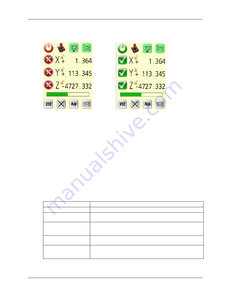
With the main screen visible it is possible to see the status of the CMM axes. 


Main screen all drives disabled  


Main screen all drives / joystick enabled , Y locked 

The  drives  may  be  enabled  by  pressing  the  red  cross  and  disabled  by  pressing  the 
green tick.  When enabled an axis may be locked and unlocked by pressing the axis 
letter.  Disabling an axis removes the drive enable signal to the amplifier and the axis 
is free to move.  Locking an axis keeps the drive enable signal on but the axis does 
not respond to joystick control. 

The joystick control may be enabled and disabled by pressing the joystick button. 

4.1.2.2 Speed wheel and main button 

The speed wheel position is shown by the green speed bar.  The position of the speed 
wheel  determines  the  maximum speed of the CMM for full joystick deflection.  It can 
be comfortably operated with the hand holding the Deva 031 unit. 

The main button may programmed in the DevaCMM Joystick tab to have a significant 
effect on joystick operation the following table shows the options. 

Main button 

Function 

None 


CNC point 

With the button pressed, a probe move with defined search speed and 
distance is started by moving the joystick in the required direction. 

Probe Arming 

The button is pressed to allow the joystick to move the machine at 
rapid speed without probe points , released to take probe points at 
armed speed. 

Deadman 

The button is pressed to allow the joystick to move the machine and 
take probe points. 

Deadman with Probe 
Arming 

The button is pressed to allow the joystick to move the machine at 
rapid speed, released to take probe points at armed speed for the 
armed timeout period. 


Summary of Contents for DEVA031

Page 1: ...V1 0 DEVA031 USB Colour Touchscreen Joystick User Guide ...

Page 2: ......

Page 3: ...ll information of a technical nature and particulars of the product and its use are given by Deva Electronic Controls Ltd in good faith However it is acknowledged that there may be errors and omissions in this manual We shall not be liable for loss or damage whatsoever arising from the use of any information or particulars in or any omissions from this document ...

Page 4: ......

Page 5: ...tallation 2 3 1 Hardware 2 3 2 Software drivers 3 3 3 System requirements 3 4 Operation 4 4 1 Main machine control screen XYZ 4 4 1 1 Turning the machine on 4 4 1 2 Joystick Operation 4 4 1 2 1 Enables and locks 5 4 1 2 2 Speed wheel and main button 5 4 1 2 3 Orientation and work piece coordinates 6 4 2 Home point screen 6 4 2 1 Config Display 7 4 2 2 Probe Head Controller operation 8 4 2 3 PC scr...

Page 6: ......

Page 7: ...the knob from left to right and forward and backwards controls the X and Y axes Twisting the knob controls the Z axis The precise relationship depends on the user orientation and the selection of machine or work piece coordinates 1 1 2 Main and auxiliary buttons The main and auxiliary buttons provide functions that are intended for use during joystick movement Typically the main button provides co...

Page 8: ...thumb of the left hand and can be easily operated whilst the joystick is in use The auxiliary button is operated by the right hand when not operating the joystick When left handed operation is selected the buttons are reversed 2 Connections The Deva031 connecting lead connects directly to the rear of the Deva031 servo amplifier via 9 pin D type connector The Deva 030 amplifier MUST have the Deva 0...

Page 9: ... device manager Follow the instructions and when requested select have disk and then browse to the directory on the installation CDROM containing the Deva031 drivers For example for XP32 Vista32 select PC interface products Deva031 Issue1 x Drivers Win32 Click ok and follow instructions to complete the first stage of the installation Windows will indicate a second time that a new USB device has be...

Page 10: ...and drive status in the case the machine is turned on or one of several machine status screens 4 1 1 Turning the machine on To turn the machine on it will be necessary to press the green on button on the off screen The following table shows the action required should this screen not be present Screen Action Next screen Supply Off Turn supply on Off Fault Press joystick Emergency stop Stop Stop Rel...

Page 11: ...shown by the green speed bar The position of the speed wheel determines the maximum speed of the CMM for full joystick deflection It can be comfortably operated with the hand holding the Deva 031 unit The main button may programmed in the DevaCMM Joystick tab to have a significant effect on joystick operation the following table shows the options Main button Function None CNC point With the button...

Page 12: ...in their relationship with the CMM axes If the user application offers work piece coordinates it is possible to select them by pressing the work piece coordinates button The joystick operation is then rotated to match the orientation of the work piece 4 2 Home point screen The home point screen allows many additional and optional features of the Deva 031 to be accessed Each feature or function is ...

Page 13: ...ight handed operation Changes the main and auxiliary buttons over Pick the icon which shows the unit held in the appropriate hand PC screen joystick buttons or touch control The PC screen view allows the screen to be viewed on the joystick This option allows control via the buttons or the touch screen Touch screen click This enables an audio click to be produced when the touch screen is pressed Sp...

Page 14: ...joystick 4 2 3 PC screen view This screen allows the contents of the PC monitor to be displayed on the Deva 031 screen The joystick allows the display to be panned and zoomed The user can optionally configure the Deva 031 to use the main and auxiliary buttons as left and right mouse buttons or to accept input to the PC from the touch screen 4 2 4 Help display This display shows the current configu...

Page 15: ...make them available when a button on the home point screen is pressed Application screen Application full screen When the App button is pressed the display will show the application screen The application screen may occupy the normal upper window area or the full screen If the full screen is shown the user must press the home point icon to return The icon will be display in one of the four corners...

Page 16: ...e screen and continue the previous task The message button will remain visible in the closed state The message can be open again by a further press of the message button The message will only clear all together when one of the possible actions presented in the message is pressed In the example below this would mean pressing the OK button Message display open Message display hidden Whilst on the me...

Page 17: ......

Page 18: ...52 Woodside Business Park Birkenhead Wirral CH41 1EL United Kingdom Tel 44 0 151 647 3222 Fax 44 0 151 647 4511 Email support deva co uk Web www deva co uk ...

Reviews: