background image

28.9.20

Fieldbus-Gateway UNIGATE

®

 CX C4Map - PROFIBUS V. 1.0

45

Deutschmann Automation GmbH & Co. KG

Communication interface PROFIBUS DP

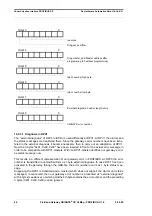
Octet 2

0

Diag.cfg_Fault
Configuration data does not correspond

Diag.ext_diag
Slave has external diagnostic data

Diag.not supported: Requested function is not  
supported in the Slave

Diag.invalid_slave_response (sets Slave 
permanently to 0).

Diag.prm_fault
Incorrect programming (identification number etc.)

Diag.master_lock (sets Master)
Slave has been programmed by another Master

Diag.Prm_req
Slave must be reprogrammed

Diag.Stat_diag
Static diagnostic (byte Diag-Bits)

Permanently set to 1

Diag.WD_ON
Response monitoring active

Diag.freeze_mode
Freeze command received

Sync_mode
Sync command received

reserved

Diag.deactivated (sets Master)

Summary of Contents for UNIGATE CX C4Map

Page 1: ...Manual Universal Fieldbus Gateway UNIGATE CX CANopen Mapping PROFIBUS DP Deutschmann Automation GmbH Co KG www deutschmann de wiki deutschmann com ...

Page 2: ...Handbuch Art Nr V4412E ...

Page 3: ...g interface 12 5 5 Commands of the Debug interface 12 6 Mode of operation of the system 13 6 1 General explanation 13 6 2 Interfaces 13 6 3 Data exchange 13 6 4 Possible data lengths 13 6 5 Startup phase 13 7 Implemented protocols in UNIGATE CX C4Map 14 7 1 Implemented protocols at CANopen interface 14 7 1 1 Functionality of the individual transport protocols 14 7 1 2 CANopen Mapping 14 7 1 2 1 Co...

Page 4: ... 1 Rotary coding switches S4 S5 serial interface 27 8 4 2 Termination CANopen 27 8 4 3 DIP Switch 27 8 5 Debug cable for UNIGATE CL 28 9 Hardware ports switches and LEDs PROFIBUS DP 29 9 1 Device labeling 29 9 1 1 Connectors 29 9 1 1 1 Connector service interface 29 9 1 1 2 Connector supply voltage and DEBUG interface 30 9 1 1 3 PROFIBUS DP connector 30 9 1 1 4 Power supply 30 9 2 LEDs 30 9 2 1 LE...

Page 5: ...4 1 Bus line with copper cable 41 14 2 Line routing shield and measures to combat interference voltage 41 14 2 1 General information on line routing 41 14 2 2 Shielding of lines 42 14 3 PROFIBUS DP 42 14 4 Description of the DPV1 DPV2 functions 42 14 4 1 DPV1 42 14 4 2 DPV2 43 14 5 Representation of the data in PROFIBUS DP 43 14 5 1 Configuration telegram 43 14 5 2 Configuration telegram 44 14 5 3...

Page 6: ...ress 51 16 7 1 PROFIBUS connection 52 16 7 2 Connection to the process device 52 16 7 3 Connecting the supply voltage 52 16 7 4 Shield connection 52 16 7 5 Project planning 52 16 7 6 Literature 52 17 Servicing 53 17 1 Returning a device 53 17 2 Downloading PC software 53 18 Annex 54 18 1 Explanations of the abbreviations 54 18 2 Hexadecimal table 55 ...

Page 7: ...n the publication is however reviewed regularly Necessary amendments are incorporated in the following editions We would be pleased to receive any improvement proposals which you may have Copyright Copyright C Deutschmann Automation GmbH Co KG 1997 2020 All rights reserved This document may not be passed on nor duplicated nor may its contents be used or disclosed unless expressly permitted Violati...

Page 8: ...y with the following requirements Scope of application Requirement applicable to Emitted interference Interference immunity Industry EN 55011 cl A 2007 EN 61000 6 2 2005 1 3 Note installation guidelines The module complies with the requirements if you 1 comply with the installation guidelines described in the User Manual when installing and oper ating the module 2 also follow the rules below on in...

Page 9: ...ve Consequently the module does not have a Declaration of Conformity in relation to the EU Machinery Directive 2 2 EU Machinery Directive The EU Machinery Directive stipulates the requirements applicable to a machine The term machine is taken to mean a totality of connected parts or fixtures see also EN 292 1 Para graph 3 1 The module is a part of the electrical equipment of the machine and must t...

Page 10: ... side It can be operated by any standard compliant PROFIBUS master The module CX C4Map PB essentially consists of the following hardware components Electrically isolated RS485 interface to the PROFIBUS DP PROFIBUS ASIC Microprocessor 89C51RD2 RAM and EPROM Serial interfaces RS232 Service interfaces Electrically isolated interface to CANopen Debug interfaces for device configuration Conceptual C4Ma...

Page 11: ...also the 0V power supply for the device In addition the two rotary swit ches S4 and S5 must be set to the 0 position The menu items Extras Upload_Config_De bug or Download_Config_Debug are used to read and write the configuration in WINGATE The exact procedure for device configuration is described in the WINGATE manual in the chap ters Connection UNIGATE via the debug interface and Configuration v...

Page 12: ...ating with 9600 baud no parity 8 data bit 1 stop bit It is not possible to change this parameter in the Protocol Developer Please consider the fact that these settings have to be in accordance with those of the PC COM interface and that the flow control protocol has to be set on none there 5 4 Possibilities with the Debug interface Usually the Protocol Developer is connected to the Debug interface...

Page 13: ...RS422 and RS485 6 3 Data exchange All data is transferred by the Gateway in dependence of the downloaded Script 6 4 Possible data lengths The table below shows the maximum transferable data PROFIBUS Input data max 244 bytes variable maximum value in this case Output data max 244 bytes variable maximum value in this case Parameters 8 bytes no user parameters Configuration data max 16 bytes dependan...

Page 14: ...TE series from Deutschmann Automation allows a cou pling between fieldbus and CANopen The gateway behaves on the CANopen side as a standard compliant master and on the PRO FIBUS DP side as a standard compliant slave so the recurring problem of connecting CANopen slave participants to a Siemens PLC with PROFIBUS DP is solved Data exchange The data exchange between fieldbus and CANopen is carried ou...

Page 15: ... the software an upload from the connected device is carried out automatically The relevant parameters for this device are shown Double click the map value After a short time a dialog is displayed with which you can edit all map entries of the gateway similar to the follo wing image You can now change the mappings delete them or add new ones right mouse button Alternatively the values can also be ...

Page 16: ...ave can monitor each other in this way If the slave does not receive a node guard request it will assume that the bus connection has been interrupted or that the master has failed Settings The default for all slaves is that no node guarding is carried out If node guarding is to be activa ted for a slave an entry enable node guarding must be added to the current configuration in WINGATE for each sl...

Page 17: ... guarding was acti vated for this slave and the slave for the node Guarding requests answered in the appropriate time Example Node guarding is activated for nodes 1 and 2 Slave 1 does not respond to node guar ding slave ID 2 works normally A mapping of the information in the fieldbus is entered in the 2nd byte Fieldbus data of the Gateway Byte 0 Byte 1 Byte 2 Byte 3 Byte 4 xx xx 0x40 xx xx 7 1 2 4...

Page 18: ... data buffer regardless of whether the data is displayed in the fieldbus or not The counter is decremented by 1 if it is not 0 7 1 2 7 Bit 6 Set Operational Toggle Bit If this bit is changed the gateway sends the Set Operational message to the slaves This feature is to be used when some slaves are slower than the master and are only ready when the master has already sent this message 7 1 2 8 Bit 5...

Page 19: ...Obj Index Index Command Auftrag Nr Knoten Nr Data Len Data 1 Read 2 Write Rest Keine Aktion Data record structure FB output data on the FB master 0 1 2 3 4 5 6 7 n Obj Index Index Status Auftrag Nr Knoten Nr Data Len Data 0 Ok 1 In Arbeit Sonst Fehler Beispiel In this example FB Idx In und FB Idx Out 8 Please note The counting starts with index 0 1st byte i H in our example the 8 corresponds to th...

Page 20: ...mmunication cycle time This period defines the SYNC interval The function can be permanently activated via the Sync Time ms Obj 1006h can be activated or set with WINGATE or temporarily via third party engineering software With WINGATE you can use the Sync Time ms Obj 1006h a time can be set in milliseconds ms With the value 0 the function is inactive 1 2 Byte 1 2 Byte 2 3 Byte 2 3 Byte 3 4 Byte 3...

Page 21: ...ng times of the data through the gateway The actual throughput time of the data from CANopen to the fieldbus or vice versa depends among other things on the following parameters Number of mappings Length of the configured PROFIBUS data Number of COB IDs used in the mappings Number of changed PROFIBUS data between 2 transmissions Number of bytes mapped in a COB ID Baud rate in PROFIBUS or CAN Due t...

Page 22: ...f bytes high 4th byte number of bates low 5th byte user data 1st byte 6th byte 2nd byte 7 Example 1st byte 0x00 2nd byte 0x02 3rd byte 0x00 4th byte 0x05 5th byte 0x01 6th byte 0x02 7th byte 0x03 8th byte 0x04 9th byte 0x05 In the fieldbus output data the data is sent to the PLC as follows sent 0x00 0x00 0x01 0x02 0x03 0x04 0x05 0x00 7 3 The trigger byte Since the data is always transmitted cyclic...

Page 23: ...ed whether the send length is also stored as a byte in the input output data area Fieldbus lengthbyte active As many bytes are sent in the send direction as are speci fied in this byte When a telegram is received the gateway enters the number of characters received 7 5 Swap word When Swap word is activated the data is exchanged word by word to and from the fieldbus I e High and low bytes in a 16 b...

Page 24: ...panel Rotary switches LEDs and termination CO In case the front panel should pop out it does not affect the device s function or quality It can be put in again without problems 8 2 Connectors 8 2 1 Connector to the external device RS interface The service RS232 interface is available on the plug concealed on the top of the device Pin assignment 3 pin screw type plug connector Pin No Name Function ...

Page 25: ...pin D SUB plug Pin No Name Function 1 2 CAN L Dominant Low 3 CAN GND CAN Ground 4 5 6 7 CAH H Dominant High 8 9 8 2 4 Power supply The device must be powered with 10 33 VDC The voltage supply is made through the 4 pole screw plug connector at the device s bottom side Please note that the devices of the series UNIGATE should not be operated with AC voltage 8 3 LEDs The Gateway UNIGATE CL CANopen fe...

Page 26: ...s of the CANopen state machine This bicolor LED shall be red and green CANopen ERROR LED red The CANopen Error LED indicates the status of the CAN physical layer and indicates errors due to missing CAN messages SYNC GUARD or HEARTBEAT ERROR LED State Description Off No error The Device is in working condition Single flash Warning limit reached At least one of the error counters of the CAN controll...

Page 27: ...ript 8 4 Switches The Gateway features 4 switches with the following functions Rotary coding switch S4 ID High for serial interface i e configmode Rotary coding switch S5 ID Low for serial interface i e configmode Termination CANopen switchable CANopen terminating resistor DIP switch Node ID and baud rate 8 4 1 Rotary coding switches S4 S5 serial interface This value is read in when the gateway is...

Page 28: ...ich is stored in the EEROM via the Script or WINGATE is used in this case That way it is also possible to set Node IDs 63 and there is no unclarity if the Node ID of the DIP Switch or the Node ID of the Script is valid In the initial state the Node ID 1 is stored in the EEROM Picture 1 DIP Switch 8 5 Debug cable for UNIGATE CL As accessory a pre configured Debug cable is available The Debug cable ...

Page 29: ...nt panel Rotary switches LEDs and termination PB In case the front panel should pop out it does not affect the device s function or quality It can be put in again without problems 9 1 1 Connectors 9 1 1 1 Connector service interface The service RS232 interface is available on the plug concealed on the top of the device Pin assignment 3 pin screw type plug connector Pin No Name Function 1 Rx 232 Re...

Page 30: ... 5 M5 DGND data reference potential 6 P5 5 V supply voltage 7 8 A Inverting input output signal from PROFIBUS 9 9 1 1 4 Power supply The device must be powered with 10 33 VDC The voltage supply is made through the 4 pole screw plug connector at the device s bottom side Please note that the devices of the series UNIGATE should not be operated with AC voltage 9 2 LEDs The Gateway UNIGATE CL PROFIBUS...

Page 31: ...number is displayed in binary notation conversion table see Annex in accordance with the table in chapter Error han dling 9 2 7 Switches The Gateway features 5 switches with the following functions Rotary coding switch S4 ID High for serial interface i e configmode Rotary coding switch S5 ID Low for serial interface i e configmode Termination Profibus switchable ProfibusDP terminating resistor Rot...

Page 32: ...y s Profibus ID 00 7D is set in hexadecimal notation Please refer to the Annex for a conversion table from decimal to hexadecimal This value is read in only once when the Gateway is activated The value can also be read out or analyzed through the Script command Get FieldbusID LongTemp 9 2 8 Debug cable for UNIGATE CL As accessory a pre configured Debug cable is available The Debug cable connects t...

Page 33: ...omatically reset If such warnings occur frequently please inform After Sales Service For user defined errors the flash frequency is 0 5 hertz The error is displayed as long as defined by Set Warning Time In the configuration mode these displays are not valid and only meant for internal use LED8 LED4 LED2 LED1 Error no resp ID Error description system error 2x sec 0 0 0 0 0 Reserved 0 0 0 1 1 Hardw...

Page 34: ...ically reset If such warnings occur frequently please inform After Sales Service For user defined errors the flash frequency is 0 5 hertz The error is displayed as long as defined by Set Warning Time In the configuration mode these displays are not valid and only meant for internal use LED8 LED4 LED2 LED1 Error no resp ID Error description 0 0 0 0 0 Reserved 0 0 0 1 1 Hardware fault 0 0 1 0 2 EERO...

Page 35: ...andard mounting channel may also be mounted vertically so that the module is mounted turned through 90 11 2 Wiring 11 2 1 Connection systems PROFIBUS The following connection systems must resp may be used when wiring the module Standard screw type plug connection power supply Debug 9 pin D SUB plug connector PROFIBUS DP a In the case of standard screw type terminals one lead can be clamped per con...

Page 36: ...ug in connection terminal strip is a combination of standard screw type terminal and plug connector The plug connection section is coded and can thus not be plugged on the wrong way round c The 9 pin D SUB plug connector is secured with two screws with 4 40 UNC thread It is best to use a screwdriver with a blade width of 3 5 mm to screw the screw tight Tightening torque 0 2 0 4 Nm 11 2 2 1 Power s...

Page 37: ... line routing in the case of bus signal and power supply lines with the aim of ensuring an EMC compliant design of your system 12 3 General information on line routing Inside and outside of cabinets In order to achieve EMC compliant routing of the lines it is advisable to split the lines into the fol lowing line groups and to lay these groups separately Group A shielded bus and data lines e g for ...

Page 38: ...ding effect In general you should always connect the shields of cables at both ends The only way of achieving good interference suppression in the higher frequency band is by connecting the shields at both ends The shield may also be connected at one end only in exceptional cases However this then achieves only an attenuation of the lower frequencies Connecting the shield at one end may be more fa...

Page 39: ... Word Value Meaning 0 PDO is not active data is defined to be used by a SDO transfer only 0x181 0x57F Allowed range for normal Rx and Tx PDO s 0xFFFE Is to be used if the master defines the COB ID s when the CANopen network is started by the master no predefined COB IDs The resulting objects used by the device are 0x1800 PDO Nr 1 Sub Index 1 of this object contains the COB ID After writing a valid...

Page 40: ...ieldbus Gateway UNIGATE CX C4Map PROFIBUS V 1 0 28 9 20 Init Object Table Create Object Set PDO Communiction Set PDO Mapping Write Object Read New CANopen Object Data Emergency Message The software does not support default objects as at CANopen V3 ...

Page 41: ...r system 14 2 1 General information on line routing Inside and outside of cabinets In order to achieve EMC compliant routing of the lines it is advisable to split the lines into the fol lowing line groups and to lay these groups separately Group A shielded bus and data lines e g for PROFIBUS DP RS232C and printers etc shielded analogue lines unshielded lines for DC voltages 60 V unshielded lines f...

Page 42: ...t one end may be more favorable if it is not possible to lay an equipotential bonding line analogue signals a few mV resp mA are to be transmitted foil shields static shields are used In the case of data lines for serial couplings always use metallic or metallized plugs and connec tors Attach the shield of the data line to the plug or connector housing If there are potential differences between th...

Page 43: ...vated via the GSD file At present our gateway only supports the func tion of the Publisher sending data to other Slaves The function Susbcriber receiving data from other Slaves is not supported at present 3 Up And Download This function is also optional for a DPV2 Slave and at present it is not supported by our gateway 4 Time synchronization Time stamp This function is also optional for a DPV2 Sla...

Page 44: ...iguration telegram Length of the data 00 1 byte word 15 16 bytes words Input output 00 specific ID format 01 input 10 output 11 input output 0 byte 1 word 0 consistent over byte word 1 consistency total length 14 5 3 Diagnosis Diagnostic data is high priority data The gateway runs an external diagnostic if it detects an internal error Representation of the information in the external diagnostic by...

Page 45: ...n is not supported in the Slave Diag invalid_slave_response sets Slave permanently to 0 Diag prm_fault Incorrect programming identification number etc Diag master_lock sets Master Slave has been programmed by another Master Diag Prm_req Slave must be reprogrammed Diag Stat_diag Static diagnostic byte Diag Bits Permanently set to 1 Diag WD_ON Response monitoring active Diag freeze_mode Freeze comma...

Page 46: ...ecessary then to carry out an adaptation at DPV1 Now the 3 bytes 0x81 0x00 0x00 have been inserted in front of the actual error message in order to be compatible with DPV1 masters With it a DPV1 master identifies our gateway s error as status message now This results in a different representation of our gateway error in PROFIBUS At DPV0 the error number is transmitted in unmodified form as 1 byte ...

Page 47: ...4 Data exchange After the Master in the diagnostic detects that the Slave is ready for data exchange it sends data exchange telegrams Either the Master stores the data in the input output direction in the address area specified during project planning or the control program must fetch or retrieve the data using specific function blocks ...

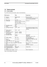
Page 48: ...d for the usual conditions not con densing 9 Storage transport temperature 40ºC 85ºC 10 Atmospheric pressure during operation during transport 795 hPa 1080hPa 660 hPa 1080hPa 11 Installation altitude 2000 m 4000 m Unrestricted Restricted Ambient temperature 40ºC 12 Relative humidity Max 80 No condensation no corrosive atmosphere 14 External power supply 10 33V DC Standard power supply unit to DIN ...

Page 49: ...h Maximum Baud rate dependent 1300 m 50 kBd 1300 m 100 kBd 640 m 200 kBd 310 m 500 kBd 112 m 1 MBd 40 m 15 m no 1200 m 93 75 kBd 1200 m 187 5 kBd 1000 m 500 kBd 400 m 1 5 MBd 200 m 1 5 MBd 100 m 6 Bus topology Line Point to point Line 7 Data rate Maximum Standard values 1Mbit s 125 kB 250 kB 500 kB 1 MB 120 kBit s 2 4 k B 4 8 k B 9 6 kBit s 19 2 kBit s 38 4 kBit s 12 Mbit s 9 6 kBit s 19 2 kBit s ...

Page 50: ...s cable is generally already installed on site 10 33 V DC power supply DIN 19240 Type file or GSD file and user manual a sample file as well as the user manual can be ordered separately or downloaded free of charge from our homepage at www deutschmann de 16 3 Installation The UNIGATE CX C4Map PB module features protection type IP20 and is thus suitable for switch cabinet use The device is designed...

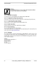
Page 51: ... tool for project planning If the required EDS file was not supplied with your project planning tool a sample file can be found on the Internet www deutschmann de 16 7 Setting the PROFIBUS address Set the PROFIBUS address at the fieldbus end of the module on the two rotary switches desig nated PROFIBUS ID High and PROFIBUS ID Low This adjustment is carried out in a hexa decimal way Example The PRO...

Page 52: ...he terminals provided for this 16 7 4 Shield connection Earth the top hat rail onto which the module has been snapped 16 7 5 Project planning Use any project planning tool for project planning If the required GSD file was not supplied with your project planning tool a sample file can be found on the Internet www deutschmann de 16 7 6 Literature We recommend that you read book Schnelleinstieg in PR...

Page 53: ...dday and from 1 pm to 4 pm Friday from 8 am to midday CET Deutschmann Automation GmbH Co KG Carl Zeiss Straße 8 D 65520 Bad Camberg Germany Central office and sales department 49 6434 9433 0 Technical support 49 6434 9433 33 Fax sales department 49 6434 9433 40 Fax technical support 49 6434 9433 44 E mail technical support support deutschmann de 17 1 Returning a device If you return a device we re...

Page 54: ...ail module and without housing cover PD Board only without DIN rail module and with housing cover AG Gateway installed in a die cast aluminum housing EG Gateway installed in a stainless steel housing IC Product group IC IC design DIL32 IC2 Product group IC2 IC design DIL32 IO8 Option I O8 16 Script memory expanded to 16KB 5V Operating voltage 5V 3 3V Operating voltage 3 3V Fieldbus CO CANopen C4 C...

Page 55: ... version X see comparison table UNIGATE IC for the respective product PBDPV0 ProfibusDPV0 PBDPV1 ProfibusDPV1 RS Serial RS232 485 422 18 2 Hexadecimal table Hex Decimal Binary 0 0 0000 1 1 0001 2 2 0010 3 3 0011 4 4 0100 5 5 0101 6 6 0110 7 7 0111 8 8 1000 9 9 1001 A 10 1010 B 11 1011 C 12 1100 D 13 1101 E 14 1110 F 15 1111 ...

Page 56: ......
Reviews: