


4.10.17
Instruction manual UNIGATE
®
FC - PROFINET 2Port V. 1.5
3
Deutschmann Automation GmbH & Co. KG
1 General introduction . . . . . . . . . . . . . . . . . . . . . . . . 8
2 The UNIGATE
FC . . . . . . . . . . . . . . . . . . . . . . . . . . 9
Technical introduction . . . . . . . . . . . . . . . . . . . . . . . . . 9
Availability . . . . . . . . . . . . . . . . . . . . . . . . . . . . . . . 9
Firmware . . . . . . . . . . . . . . . . . . . . . . . . . . . . . . . . 9
The serial standard Interface . . . . . . . . . . . . . . . . . . . . . . 9
The synchronous serial Interface . . . . . . . . . . . . . . . . . . . . 9
The Debug-Interface . . . . . . . . . . . . . . . . . . . . . . . . . . 10
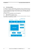
2.7
®
FC hardware survey . . . . . . . . . . . . . . . . . . . . 10
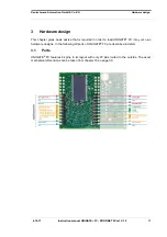
3 Hardware design. . . . . . . . . . . . . . . . . . . . . . . . . . 11
Ports . . . . . . . . . . . . . . . . . . . . . . . . . . . . . . . . . . 11
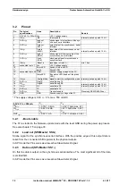
Pinout . . . . . . . . . . . . . . . . . . . . . . . . . . . . . . . . . 12
-Boot enable . . . . . . . . . . . . . . . . . . . . . . . . . . . . . . 12
Load out (SPI-Master: SS0-) . . . . . . . . . . . . . . . . . . . . . 12
Data out (SPI-Master: SS1-). . . . . . . . . . . . . . . . . . . . . . 12
Data In (SPI: MISO) . . . . . . . . . . . . . . . . . . . . . . . . . . 13
Load In (SPI: MOSI) . . . . . . . . . . . . . . . . . . . . . . . . . . 13
Clock (SPI: SCK) . . . . . . . . . . . . . . . . . . . . . . . . . . . 13
-Reset In . . . . . . . . . . . . . . . . . . . . . . . . . . . . . . . . 13
Errror LED . . . . . . . . . . . . . . . . . . . . . . . . . . . . . . . 13
Ground. . . . . . . . . . . . . . . . . . . . . . . . . . . . . . . . . 13
3.2.10 State-LED . . . . . . . . . . . . . . . . . . . . . . . . . . . . . . . 13
3.2.11 -Config Mode . . . . . . . . . . . . . . . . . . . . . . . . . . . . . 13
3.2.12 DbgTX, DbgRx. . . . . . . . . . . . . . . . . . . . . . . . . . . . . 14
3.2.13 TX, RX . . . . . . . . . . . . . . . . . . . . . . . . . . . . . . . . . 14
3.2.14 TE . . . . . . . . . . . . . . . . . . . . . . . . . . . . . . . . . . . 14
Software . . . . . . . . . . . . . . . . . . . . . . . . . . . . . . . . 14
Basic line of proceeding . . . . . . . . . . . . . . . . . . . . . . . . 14
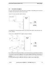
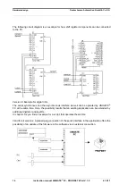
Connection examples . . . . . . . . . . . . . . . . . . . . . . . . . . 15
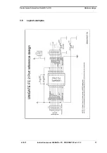
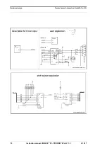
Layout examples . . . . . . . . . . . . . . . . . . . . . . . . . . . . 17
3.7
Handling (mounting the UNIGATE
®
FC on the carrier board) . . . . . 19
4 The serial interface . . . . . . . . . . . . . . . . . . . . . . . . 20
Overview . . . . . . . . . . . . . . . . . . . . . . . . . . . . . . . . 20
4.2
FC . . . . . . . . . . . . . . . . . . . 20
Initialization of the serial interface . . . . . . . . . . . . . . . . . . . 20
Use of the serial interface . . . . . . . . . . . . . . . . . . . . . . . 20
Further operation modes . . . . . . . . . . . . . . . . . . . . . . . . 20
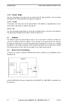
5 Synchronous serial interface . . . . . . . . . . . . . . . . . . . 21
Shift register operation . . . . . . . . . . . . . . . . . . . . . . . . . 21
5.1.1
Example-Script . . . . . . . . . . . . . . . . . . . . . . . . . . . . 21


