background image

SNAPSHOT EXAMPLES

THIS PAGE INTENTIONALLY LEFT BLANK

7-18

All information subject to change without notice.

(Rev. June 2005)

7SE60 0506

Copyright © 2005 DETROIT DIESEL CORPORATION

Summary of Contents for Series 60 EGR

Page 1: ......

Page 2: ... to be used in conjunction with the DDEC III IV Single ECM Troubleshooting Guide and the DDEC V Single ECU Troubleshooting Guide Series 60 Detroit Diesel DDC DDEC and the spinning arrows design are registered trademarks of Detroit Diesel Corporation Diagnostic Link is a registered trademarks of the Detroit Diesel Corporation ...

Page 3: ...lized in multiple areas This manual is designed with that thought in mind This Series 60 EGR Technician s Guide will provide you with concentrated information that will allow you to excel in EGR technology The Series 60 EGR Technician s Guide supports the October 2002 through current production Series 60 EGR engines Acronyms are used throughout this guide acronyms which support both the DDEC IV an...

Page 4: ...ii All information subject to change without notice Rev June 2005 7SE60 0506 Copyright 2005 DETROIT DIESEL CORPORATION ...

Page 5: ... 1 8 DDEC V COMPONENTS 8 1 9 DDEC V CODES 9 1 10 DDEC V TESTING 10 1 APPENDIX A LIST OF ACRONYMS A 1 APPENDIX B DDEC IV WIRING SCHEMATICS B 1 APPENDIX C ENGINE DIAGNOSTIC QUESTIONNAIRE C 1 APPENDIX D SERVICE INFORMATION LETTERS D 1 APPENDIX E DDEC IV ECM OVERVIEW AND VEHICLE INTERFACE HARNESS E 1 All information subject to change without notice Rev June 2005 iii 7SE60 0506 Copyright 2005 DETROIT D...

Page 6: ...TABLE OF CONTENTS iv All information subject to change without notice Rev June 2005 7SE60 0506 Copyright 2005 DETROIT DIESEL CORPORATION ...

Page 7: ...DDEC V Series 60 EGR engine is the Detroit Diesel Diagnostic Link DDDL This tool will provide you all the help you will need as it contains proper troubleshooting information for all products NOTE It is absolutely critical that you understand the EGR system to be qualified to offer any type of proper diagnostics Do not waste time trying to troubleshoot a DDC product you are not qualified to troubl...

Page 8: ... for broken wiring connectors Ƒ Check for poor mating of the connector halves or terminals not fully seated in the connector body backed out terminals Ƒ Look for improperly formed or damaged terminals All connector terminals in the problem circuit should be carefully inspected to determine proper contact tension Use a mating terminal to test the contact tension Ƒ Check for electrical system interf...

Page 9: ...ian Ƒ Intermittent Problems Talk to the operator driver Be specific Ƒ Develop your own Driver Questionnaire see Figure 1 1 NOTE A full page copy of the questionnaire can be found in Appendix C All information subject to change without notice Rev June 2005 1 3 7SE60 0506 Copyright 2005 DETROIT DIESEL CORPORATION ...

Page 10: ...INTRODUCTION Figure 1 1 Drivers Questionnaire 1 4 All information subject to change without notice Rev June 2005 7SE60 0506 Copyright 2005 DETROIT DIESEL CORPORATION ...

Page 11: ...problem occurred 4 Does the problem occur only at specific operating conditions If so at what load Is it light medium or heavy 5 Does the problem occur at a specific engine operating temperature If so at what engine temperature 6 Does the problem occur at a specific engine operating altitude If so at what altitude 7 Does the problem occur only when above or below specific outside temperatures In w...

Page 12: ...with the ignition wiring 4 Operate the engine under similar load conditions Check the fuel system for restrictions primary filter and fuel tanks for foreign objects blocking the fuel supply Also check the air system Utilize the DDDL snapshot feature 5 Operate the engine at this temperature while attempting to duplicate the problem Use the snapshot feature on the DDDL 6 If possible troubleshoot the...

Page 13: ...ne exhaust gases will dilute the incoming air by displacing some of the oxygen in the air being supplied through the intake manifold Less oxygen results in a slower fuel burn which reduces the peak cylinder temperature permitting reduced nitrogen oxides NOx emissions Figure 2 1 illustrates how the components of a EGR system function Figure 2 1 EGR System All information subject to change without n...

Page 14: ...3 1 EGR Valve Actuator 5 EGR Gas Delivery Pipe 8 EGR Cooler 2 VNT Actuator 6 S Pipe 9 High Flow Water Pump 3 VNT Turbocharger 7 EGR Valve 4 Delta Pressure Sensor Figure 2 2 Pre 2004 Right Side View 2 2 All information subject to change without notice Rev June 2005 7SE60 0506 Copyright 2005 DETROIT DIESEL CORPORATION ...

Page 15: ...ifold Air Temperature Sensor 2 EGR Mixer 5 Barometric Pressure Sensor 3 Intake Manifold 6 Turbo Boost Pressure Sensor Figure 2 3 Pre 2004 Left Side View All information subject to change without notice Rev June 2005 2 3 7SE60 0506 Copyright 2005 DETROIT DIESEL CORPORATION ...

Page 16: ...he enhancements such as tube and shell EGR cooler redesigned delivery pipe EGR valve and venturi tube NOTE You may also access 18SP documents after logging into the DDC Extranet by clicking on Support On Highway Service Information Special Publications 18SPs 1 Tube and Shell EGR Cooler 3 Delivery Pipe 2 EGR Valve 4 Venturi Tube Figure 2 4 Enhanced DDEC IV 2004 EGR Engine 2 4 All information subjec...

Page 17: ...ement The ECM receives electronic inputs during vehicle operation via engine and vehicle mounted sensors Refer to Appendix E for a view of the DDEC IV ECM and related harness connectors DDEC IV ECM engine management benifits are Ƒ Excellent engine performance Ƒ Optimum fuel economy Ƒ Emission levels that meet current laws without after treatment Ƒ Engine diagnostics Ƒ Simple programming All inform...

Page 18: ...s are application dependent Two system components are required for proper operation of EGR valve and VNT control system Ƒ 12V or 24V power supply Ƒ DDEC IV ECM PWM 2 Y1 EGR and PWM 4 X2 VNT Figure 2 5 EGR Valve and VNT Control System 2 6 All information subject to change without notice Rev June 2005 7SE60 0506 Copyright 2005 DETROIT DIESEL CORPORATION ...

Page 19: ...closure increases the EGR flow rate PWM is high Ƒ Less vane closure decreases the EGR flow rate PWM is low Ƒ Enhanced engine brake capability The following conditions are present when vane positions are at 90 PWM See Figure 2 6 Ƒ Regulated air pressure to the VNT actuator from the VPOD is at the maximum Ƒ Regulated exhaust restriction is at the maximum Ƒ EGR flow is at maximum while operating in E...

Page 20: ...ated air pressure is supplied to the VNT actuator from the VPOD Ƒ Exhaust gas restriction is moderate Ƒ EGR flow is increased while operating in EGR Mode Figure 2 7 Regulated Air Pressure to the VNT 2 8 All information subject to change without notice Rev June 2005 7SE60 0506 Copyright 2005 DETROIT DIESEL CORPORATION ...

Page 21: ...ure 2 8 Ƒ Air pressure is not supplied to the VNT actuator from the VPOD Ƒ Exhaust gas restriction is minimal Ƒ EGR flow is minimal while operating in EGR Mode Figure 2 8 No Air Pressure to the VNT All information subject to change without notice Rev June 2005 2 9 7SE60 0506 Copyright 2005 DETROIT DIESEL CORPORATION ...

Page 22: ... pin joint of the turbine external arm Rotation of external arm simultaneously rotates several pivoting nozzle vanes positioned inside turbine housing at the outer periphery of turbine wheel This adjusts turbocharger speed boost and EGR flow in accordance with DDEC engine management control NOTE VNT actuator is spring loaded If air pressure is lost the actuator will open the VNT vanes resulting in...

Page 23: ...ngine acceleration The TBS sensor is supplied a 5 volt reference signal by ECM and returns a voltage signal to the ECM relative to turbo boost pressure Return voltage increases as boost pressure increases Operating values are 0 10 5 0 V during normal engine operation Figure 2 10 Turbocharger Boost Sensor All information subject to change without notice Rev June 2005 2 11 7SE60 0506 Copyright 2005 ...

Page 24: ...er and recirculates a fraction of the engine exhaust gases to the intake manifold for purposes of engine emission control When the EGR valve is closed exhaust flows from the exhaust manifold past the turbine wheel into the VNT and out exhaust system in traditional way See Figure 2 11 to view a pre 2004 EGR valve and see Figure 2 12 to view enhanced EGR valve NOTE The EGR actuator is spring loaded ...

Page 25: ...ced EGR Valve EGR Valve Actuator The EGR valve actuator see Figure 2 13 regulates EGR butterfly valve Figure 2 13 EGR Valve Actuator All information subject to change without notice Rev June 2005 2 13 7SE60 0506 Copyright 2005 DETROIT DIESEL CORPORATION ...

Page 26: ...heat from exhaust gases that enter the EGR cooler See Figure 2 14 See Figure 2 15 for a view of the current EGR cooler 1 Pre 2004 EGR Cooler 2 Enhanced EGR Cooler Figure 2 14 Pre 2004 EGR Cooler and Enhanced EGR Cooler 2 14 All information subject to change without notice Rev June 2005 7SE60 0506 Copyright 2005 DETROIT DIESEL CORPORATION ...

Page 27: ...EGR cooler core transfers the heat from the exhaust gases to the engine cooling system as the gases are sent to the EGR charge air mixer The gases are then mixed with incoming air from the charge air cooler before being sent to the intake manifold All information subject to change without notice Rev June 2005 2 15 7SE60 0506 Copyright 2005 DETROIT DIESEL CORPORATION ...

Page 28: ...he sensor is supplied a 5 volt reference signal from the ECM and returns a voltage signal to ECM relative to pressure difference across the Venturi tube Return sensor voltage increases as pressure differential increases during engine operation operating values are 0 23 4 77 V 1 Thermostat Housing 2 Delta P Sensor Figure 2 16 Delta P Sensor 2 16 All information subject to change without notice Rev ...

Page 29: ...ivery pipe to the charge air mixer See Figure 2 17 to view pre 2004 delivery pipe and see Figure 2 18 to view enhanced delivery pipe The ECM uses this information along with temperature and density of exhaust gases to determine precise EGR mass flow rate See Figure 2 19 for pre 2004 venturi tube and see Figure 2 20 for enhanced venturi tube Figure 2 17 Pre 2004 Delivery Pipe All information subjec...

Page 30: ...DDEC IV COMPONENTS Figure 2 18 Enhanced Delivery Pipe 2 18 All information subject to change without notice Rev June 2005 7SE60 0506 Copyright 2005 DETROIT DIESEL CORPORATION ...

Page 31: ...SERIES 60 EGR TECHNICIAN S MANUAL Figure 2 19 Pre 2004 Venturi Tube All information subject to change without notice Rev June 2005 2 19 7SE60 0506 Copyright 2005 DETROIT DIESEL CORPORATION ...

Page 32: ...DDEC IV COMPONENTS Figure 2 20 Enhanced Venturi Tube 2 20 All information subject to change without notice Rev June 2005 7SE60 0506 Copyright 2005 DETROIT DIESEL CORPORATION ...

Page 33: ...nsor is supplied a 5 volt reference signal from the ECM and returns a voltage signal to the ECM relative to exhaust gas temperatures in the EGR delivery pipe Sensor return voltage decreases as exhaust gas temperature increases sensor operating values are 0 10 5 0 V See Figure 2 21 to view the sensor with connector Figure 2 21 EGR Tempertaure Sensor All information subject to change without notice ...

Page 34: ... diffuses EGR gases evenly to each cylinder Sensors are mounted within the intake manifold to monitor air temperature and boost pressure See Figure 2 22 for a view of the pre 2004 EGR mixer and see Figure 2 23 for a view of the enhanced EGR mixer Figure 2 22 Pre 2004 EGR Mixer 2 22 All information subject to change without notice Rev June 2005 7SE60 0506 Copyright 2005 DETROIT DIESEL CORPORATION ...

Page 35: ...or a more dense charge of air to be delivered to engine Turbocharger Compressor Inlet Temperature Sensor Turbocharger Compressor Inlet Temperature Senor TCI is a DDC part and is installed by the truck manufacturer within piping between the air filter and turbocharger inlet The TCI sensor which is used to control EGR operation in high humidity and heat conditions that may cause damage to the engine...

Page 36: ... water pump to improve the coolant flow for added heat dissipation NOTE The high flow water pump is not interchangeable between EGR and non EGR engines 2 24 All information subject to change without notice Rev June 2005 7SE60 0506 Copyright 2005 DETROIT DIESEL CORPORATION ...

Page 37: ...urately control exhaust gas flow Transition from EGR to Boost Transition from EGR to Boost Mode occurs when the engine is generating power while flowing EGR and DDEC requests to close the EGR valve and generate power based upon boost pressure Braking Mode Braking Mode occurs when the engine is absorbing energy power through an internal engine braking device The power for the engine brake is accomp...

Page 38: ...ler or delivery pipe Ƒ VNT vane position controlled by intake manifold boost pressure and limited by the turbocharger speed Red Exhaust Gas Yellow Vehicle Air VPODs Blue No EGR Flow Figure 3 1 Boost Mode EGR Valve Closed 3 2 All information subject to change without notice Rev June 2005 7SE60 0506 Copyright 2005 DETROIT DIESEL CORPORATION ...

Page 39: ...ressure supplied by the EGR VPOD to the EGR actuator opens the butterfly valve See Figure 3 2 Once the EGR butterfly valve opens the EGR gases flow through the EGR cooler and into the delivery pipe Red Exhaust Gas Yellow Vehicle Air VPODs Orange Cooled Exhaust Gas Green Coolant Flow Figure 3 2 EGR Mode All information subject to change without notice Rev June 2005 3 3 7SE60 0506 Copyright 2005 DET...

Page 40: ... FROM BOOST MODE TO EGR MODE The EGR valve is actuated by the ECM Initiation of EGR requires minimum engine speed and boost pressure air flow in order to transition into EGR mode without an abrupt drop in air fuel ratio Once minimum RPM and boost levels are attained the ECM sends a signal via PWM 2 see Figure 3 3 to initiate the valve opening event by providing air pressure to the EGR actuator Fig...

Page 41: ... gas enters the EGR cooler at high temperatures and is cooled by the engine coolant system to increase the density of the gas Figure 3 4 Coolant Flow through the EGR Cooler All information subject to change without notice Rev June 2005 3 5 7SE60 0506 Copyright 2005 DETROIT DIESEL CORPORATION ...

Page 42: ... venturi pressure levels are measured from the two venturi taps or ports The delta pressure measurement in conjunction with the EGR temperature determines the EGR flow rate Figure 3 5 EGR Measurement 3 6 All information subject to change without notice Rev June 2005 7SE60 0506 Copyright 2005 DETROIT DIESEL CORPORATION ...

Page 43: ...sed to change the EGR rate The VNT is controlled via the DDEC PWM 4 see Figure 3 6 which regulates the air pressure to change the VNT vane position Figure 3 6 EGR Valve and VNT Control System All information subject to change without notice Rev June 2005 3 7 7SE60 0506 Copyright 2005 DETROIT DIESEL CORPORATION ...

Page 44: ...ncrease or decrease to the EGR flow rate See Figure 3 7 Red Exhaust Gas Yellow Vehicle Air VPODs Orange Cooled Exhaust Gas Green Coolant Flow Figure 3 7 VNT Control Flow 3 8 All information subject to change without notice Rev June 2005 7SE60 0506 Copyright 2005 DETROIT DIESEL CORPORATION ...

Page 45: ...the calibration determines is not normal For example If the ECM commands the EGR valve to open or close the ECM monitors the EGR flow devices for confirmation that flow has begun or ended Logic codes identify a condition NOT a component Component Sensor Codes This code is activated when a specific component failure exists This is most commonly seen as a high volt or low volt code for a specific de...

Page 46: ...e Position Sensor Input Voltage High 22 91 4 Throttle Position Sensor Input Voltage Low 23 174 3 Fuel Temperature Sensor Input Voltage High 24 174 4 Fuel Temperature Sensor Input Voltage Low 25 Reserved for No Codes 26 25 11 Aux Shutdown 1 Active 26 61 11 Aux Shutdown 2 Active 27 105 3 Intake Manifold Temperature Sensor Input Voltage High 27 171 3 Ambient Air Temperature Sensor Input Voltage High ...

Page 47: ...epsonding Jake Mode 39 147 14 EGR Flow too Low 41 21 0 Too Many SRS missing TRS 42 21 1 Too few SRS missing SRS 43 111 1 Coolant Level Low 44 105 0 Intake Manifold Temperature High 44 110 0 Coolant Temperature High 44 172 0 Air Inlet Temperature High 44 175 0 Oil Temperature High 105 14 Inlet Manifold Temperature Derate 110 14 Coolant Temperature Derate 45 100 1 Oil Pressure Low 46 168 1 ECM Batte...

Page 48: ...hanical System Not Responding Properly W3 62 54 3 Aux Output 6 Short to Battery X3 62 54 4 Aux Output 6 Open Circuit X3 62 54 7 Aux Output 6 Mechanical System Not Responding Properly X3 62 55 3 Aux Output 7 Short to Battery Y3 62 55 4 Aux Output 7 Open Circuit Y3 62 55 7 Aux Output 7 Mechanical System Not Responding Properly Y3 62 56 3 Aux Output 8 Short to Battery A1 62 56 4 Aux Output 8 Open Cir...

Page 49: ...n 73 227 3 Aux Analog Input 1 Voltage High ESS Transmission 73 227 4 Aux Analog Input 1 Voltage Low ESS Transmission 74 70 4 Optimized Idle Safety Loop Short to Ground 74 99 0 Oil Filter Restriction High 75 168 0 ECM Battery Voltage High 75 214 0 RTC Backup Battery Voltage High 75 232 0 Sensor Supply Voltage High 76 121 0 Engine Overspeed With Engine Brake 77 100 0 Engine Oil Pressure High 77 102 ...

Page 50: ...nding Indicates EGR flow requested by DDEC and no EGR flow detected SID 146 FMI 7 will be set by the ECM if the signal from the Delta P sensor and EGR temperature sensor indicate EGR flow is below a minimum allowable flow when the ECM is in EGR Mode for a period greater than 50 seconds Response The CEL will be illuminated and the system will be forced into Boost Mode EGR is Disabled for the remain...

Page 51: ... mechanical failure open Ƒ Plugged Delta P lines Failure Mode SID 146 FMI 12 EGR Leak Boost Jake Indicates No EGR flow requested by DDEC and EGR flow is detected while braking SID 146 FMI 12 will be set by the ECM if the signal from the Delta P sensor and EGR temperature sensor indicate EGR flow is above a maximum allowable flow when the ECM is in Jake Mode for a period greater than 50 seconds Res...

Page 52: ...charger actuator Ƒ Mechanical failure VNT vane set Ƒ Restricted air intake including air filter Failure Mode SID 147 FMI 7 Excessive EGR Flow EGR Mode VNT Vanes Not Responding EGR Mode Indicates EGR flow requested by DDEC and excessive EGR flow detected SID 147 FMI 7 will be set by the ECM if the signal from the Delta P sensor and EGR temperature sensor indicate EGR flow is above a desired flow fo...

Page 53: ...eriod greater than 50 seconds Response The CEL will illuminate and a fault message will be generated Possible Causes Ƒ Defective VPOD Ƒ Exhaust leaks at S pipe or exhaust manifold Ƒ Leaks in charge air cooler system CAC hoses tubes or clamps Ƒ Leaking or low air supply to VPOD Ƒ Mechanical failure EGR valve Ƒ Mechanical failure turbocharger actuator Ƒ Mechanical failure turbocharger failure Ƒ Mech...

Page 54: ...ng at the S pipe Ƒ Leaking air lines from the VPOD to the actuators insufficient air supply Ƒ Leaking or low vehicle air supply to the VPODs Ƒ Plugged Delta P ports Ƒ VPOD mechanical failure Ƒ VNT vanes actuator mechanical failure Diagnosing Flash Code 49 Failure Mode FMI 0 Turbo Compressor Out Temperature High Indicates Turbocharger Compressor Inlet temperature or Turbocharger Compressor Outlet t...

Page 55: ...esponse The CEL will be illuminated and the engine will be torque limited to protect the turbocharger and charge air cooler EGR Delta Pressure Sensor Failure Modes PID 411 FMI 3 Voltage High and FMI 4 Voltage Low Response The CEL will be illuminated and the system will be forced into boost mode The engine will be torque limited during this fault EGR Temperature Sensor Failure Modes PID 412 FMI 3 V...

Page 56: ... Codes When these codes are logged and turn on both the check engine and stop engine lights This alerts the operator that continued engine operation under those conditions will result in engine damage Coolant Temperature High PID 110 FMI 0 indicates the coolant temperature has risen above the programmed value in the ECM The temperature limits are listed in Table 4 1 Oil Pressure Low PID 100 FMI 1 ...

Page 57: ...rature limits Year Start Derate EGR Off CEL SEL Coolant Temperature 2002 214 F 101 C 221 F 105 C 223 F 106 C 225 F 107 C 2004 219 F 103 C 228 F 108 C 227 F 108 C 229 F 109 C Compressor Discharge Temperatureat Sea Level 2002 453 F 223 C 554 F 290 C 2004 445 F 229 C 515 F 268 C Intake Manifold Temperature 2002 201 F 93 C 213 F 100 C 218 F 103 C 2004 203 F 95 C 216 F 102 C 212 F 100 C Oil Temperature...

Page 58: ...DDEC IV DIAGNOSTIC CODES THIS PAGE INTENTIONALLY LEFT BLANK 4 14 All information subject to change without notice Rev June 2005 7SE60 0506 Copyright 2005 DETROIT DIESEL CORPORATION ...

Page 59: ... asp and browse for Technical Service Letter 04 TS 32 Ƒ Service Information Letter 04 TS 62 For detailed information please visit the Detroit Diesel Technical Service Letter Web Page at http 192 135 85 10 cust sletr revised_2004 asp and browse for Technical Service Letter 04 TS 62 NOTE You may also access these TS letters after logging into the DDC Extranet by clicking on Support On highway Servic...

Page 60: ...levels SID 147 codes and black exhaust smoke checks For detailed information please visit the Detroit Diesel Technical Service Letter Web Page at http 192 135 85 10 cust sletr revised_2004 asp and browse for Technical Service Letter 05 TS 01 5 2 All information subject to change without notice Rev June 2005 7SE60 0506 Copyright 2005 DETROIT DIESEL CORPORATION ...

Page 61: ...y 4 Visually inspect the air inlet for restrictions If the air inlet has restrictions clean as necessary 5 Perform Test A in the Testing Procedure section 6 Perform the checks in the Exhaust Gas Recirculation System Basic Checks section Refer to the Exhaust Gas Recirculation System Basic Checks for Series 60 Engines section of the DDDEC III IV Single ECM Troubleshooting Guide 6SE497 7 Test drive t...

Page 62: ...sually inspect the air inlet hoses for soft or collapsed areas If the air inlet hoses are damaged replace as necessary 4 Visually inspect the air inlet for restrictions If the air inlet has restrictions clean as necessary 5 Visually inspect the entire length of the breather tube for kinks If the breather tube has kinks repair as necessary 6 Measure the fuel pressure under heavy loads a If the fuel...

Page 63: ...Higher ambient temperatures and loads will increase the frequency of DDEC applying this derate logic If the derate is occurring only occasionally this is Typical If the derate occurs more than Typical for given operating conditions continue investigation for possible defects a If considered Typical clear Fault Codes and return the engine to service b If determined to be abnormal frequency perform ...

Page 64: ...n the engine lubrication oil pan 4 Refill the lubrication oil pan with 32 quarts of approved engine oil and visually inspect the oil dipstick marking a If the oil dipstick marking is incorrect replace the dipstick with a proper dipstick b If the oil dipstick marking was correct testing is complete Engine Vibration Perform the following steps for Engine Vibration 1 Using a 0 060 in feeler gage meas...

Page 65: ...f the pressure is at 27 psi or higher continue to step 4 4 Activate EGR VPOD PWM 2 to 90 using the DDDL 5 Monitor the boost psi pressure for pressure drops when the EGR valve opens NOTE The pressure should have dropped significantly to approximately 9 psi a If the air pressure dropped to 9 psi no further testing is required and Test A has been completed b If the pressure only dropped slightly perf...

Page 66: ... F 76 C coolant temperature 2 Activate the VPOD outputs to 90 and then back it down to 7 using the DDDL Visually inspect the VNT and EGR valve for proper rod travel full travel to stops a If the VNT is not functioning properly verify VNT vanes are moving freely For detailed information please visit the Detroit Diesel Technical Service Letter Web Page at http 192 135 85 10 cust sletr revised_2004 a...

Page 67: ...a If Delta P counts read 86 135 verify that the EGR pipes and hoses are correctly assembled from the EGR tube to the Delta P sensor Reversed hoses or pipes will create black smoke and surging Go to step 3 b b Also inspect carefully for split or leaking pipes or hoses in the EGR mixer tube from the EGR cooler to the intake manifold If hoses and pipes are correct perform check VPOD output pressure r...

Page 68: ...rom the EGR and VNT Variable Nozzle Turbine actuators 2 Install pressure gauges accurate to within 1 4 kPa 0 2 psi at the outlet of the EGR and VNT hoses Use two gauges or test separately 3 Using the DDDL DDR activate PWM 2 EGR and PWM 4 VNT duty cycles and monitor the output pressure from the VPOD 4 Test activating 11 duty cycle Pressure 106 134 kPa 15 4 19 4 psi Go to steps 5 a and 5 b 5 10 All ...

Page 69: ...o the Check Variable Output Pressure Device Part Number and Supply Voltage section 2 Perform a Check Variable Output Pressure Device Part Number and Supply Voltage Check Variable Output Pressure Device Part Number and Supply Voltage The following checks should be performed for the VPOD part number and supply voltage 1 Check the VPOD label to determine if it is 12V or 24V compatible 2 Unplug VPOD s...

Page 70: ... PWM 4 VNT and ensure a Activating 11 duty cycle VDC 90 of the VPOD supply voltage 1 volt e g voltage to VPOD 13 8V 0 9 12 42V therefore 11 42V to 13 42V at PWM is acceptable b Activating 90 duty cycle VDC 10 of the VPOD supply voltage 1 volt e g voltage to VPOD 13 8V 0 1 1 38V therefore 0 38V to 2 38V at PWM is acceptable 6 Note any air leakage when PWMs are activated to 90 and correct the leaks ...

Page 71: ...ate the fueling to the engine If the customer complaint was a power loss it could be explained that loss of power was done by the ECM to protect other engine components 5 If the issue is not related to the EGR system components or if assistance is needed contact Detroit Diesel Customer Support Center at 313 592 5800 Verification Follow these steps to test 1 Reassemble connectors or components 2 St...

Page 72: ...DDEC IV TESTING THIS PAGE INTENTIONALLY LEFT BLANK 5 14 All information subject to change without notice Rev June 2005 7SE60 0506 Copyright 2005 DETROIT DIESEL CORPORATION ...

Page 73: ... down menu and select the New option by clicking once with the left mouse button 3 Upon choosing the New option a Record Snapshot box will appear in the upper left section of your screen 4 The Record Time will be counting from the second you clicked on the New option All information subject to change without notice Rev June 2005 6 1 7SE60 0506 Copyright 2005 DETROIT DIESEL CORPORATION ...

Page 74: ...he snapshot click once with the left mouse button on the Annotate selection version 4 1 or later 6 When you have completed recording the data you wish to save click once with the left mouse button on the Stop Recording ESC box 7 Immediately upon selecting the Stop Recording ESC option a dialog box will appear asking if you wish to save your changes If you want to save the recorded data to your har...

Page 75: ...e Yes option the Save As dialog box will appear on your screen A suggested file name will appear outlined in blue in the File Name box All information subject to change without notice Rev June 2005 6 3 7SE60 0506 Copyright 2005 DETROIT DIESEL CORPORATION ...

Page 76: ...n your PC by changing the location designated in the Save In box You may save the file to your A drive for example Once the file has been saved the process is complete USING SNAPSHOT REPLAY CONTROLS 1 To replay a snapshot go to the Snapshot drop down menu and select Open You should not be connected to a vehicle when replaying a snapshot 2 A dialog box will appear listing all the available snapshot...

Page 77: ...ck of the left mouse button The selected file name will now appear in the File Name box 4 Click once with the left mouse button on the Open box in the lower right of the dialog box 5 When you have opened a snapshot replay controls will appear at the bottom of the DDDL window you opened All information subject to change without notice Rev June 2005 6 5 7SE60 0506 Copyright 2005 DETROIT DIESEL CORPO...

Page 78: ...ts current position and the instruments show the appropriate readings The event window also changes during the replay to show the most recent event 7 Stop the replay at a particular point of interest by clicking on Pause The instruments will show the values at the time the replay was stopped 8 Move to a specific time in the replay by dragging the replay slider button As you drag the slider the tim...

Page 79: ...ot access the injector response time window or the cylinder cutout window in snapshot mode Samples of windows that may be activated include Normal Instrumentation Window Diagnostic Instrumentation Window All information subject to change without notice Rev June 2005 6 7 7SE60 0506 Copyright 2005 DETROIT DIESEL CORPORATION ...

Page 80: ...DDDL SNAPSHOTS Graph Window User Window 6 8 All information subject to change without notice Rev June 2005 7SE60 0506 Copyright 2005 DETROIT DIESEL CORPORATION ...

Page 81: ...SERIES 60 EGR TECHNICIAN S MANUAL Fault Codes Window All information subject to change without notice Rev June 2005 6 9 7SE60 0506 Copyright 2005 DETROIT DIESEL CORPORATION ...

Page 82: ...DDDL SNAPSHOTS THIS PAGE INTENTIONALLY LEFT BLANK 6 10 All information subject to change without notice Rev June 2005 7SE60 0506 Copyright 2005 DETROIT DIESEL CORPORATION ...

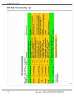
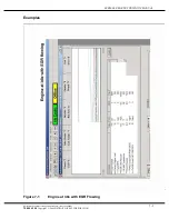
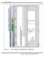
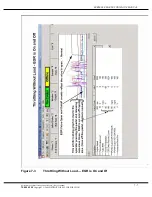
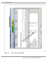
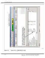
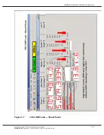
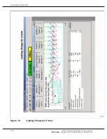
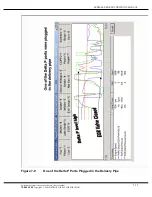
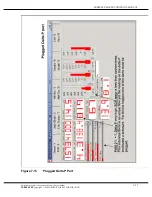
Page 83: ... Ƒ Throttling without load EGR is on and off See Figure 7 3 Ƒ 1500 rpm throttling no EGR See Figure 7 4 Ƒ EGR Valve stuck open See Figure 7 5 Ƒ 147 14 EGR Flow too Low See Figure 7 6 Ƒ 146 2 EGR leak boost See Figure 7 7 Ƒ Leaking Charge Air Cooler See Figure 7 8 Ƒ Delta P port plugged graph See Figure 7 9 Ƒ Normal Acceleration Automatic Transmission See Figure 7 10 Ƒ Typical EGR flow loaded See F...

Page 84: ...r leaking includes sensor mounting o rings Ƒ The sensor being defective is the least likely Ƒ Incorrectly wired replacement sensor Low Delta P with Flow Demand PWM2 greater than 7 and less than 90 If the EGR valve is open and the EGR temperature is elevated there should EGR flow If the Delta P sensor is registering a low differential pressure in this condition it is likely that the pressure signal...

Page 85: ...ould try to respond to the false signal VPOD The Variable Pressure Orfice or Output Device is used to control the pressure to the actuators used for the EGR valve and turbocharger vane position The most common failure is external leakage of air You can hear the leak when you activate the PWM for each VPOD Relative Humidity Turbo Compressor Inlet Temperature Sensor This sensor is a DDC part install...

Page 86: ...SNAPSHOT EXAMPLES EGR Flow Troubleshooting Tips 7 4 All information subject to change without notice Rev June 2005 7SE60 0506 Copyright 2005 DETROIT DIESEL CORPORATION ...

Page 87: ...RIES 60 EGR TECHNICIAN S MANUAL Examples Figure 7 1 Engine at Idle with EGR Flowing All information subject to change without notice Rev June 2005 7 5 7SE60 0506 Copyright 2005 DETROIT DIESEL CORPORATION ...

Page 88: ...SNAPSHOT EXAMPLES Figure 7 2 Idle Cold Engine No EGR Demand No EGR Flow 7 6 All information subject to change without notice Rev June 2005 7SE60 0506 Copyright 2005 DETROIT DIESEL CORPORATION ...

Page 89: ...RIES 60 EGR TECHNICIAN S MANUAL Figure 7 3 Throttling Without Load EGR is On and Of All information subject to change without notice Rev June 2005 7 7 7SE60 0506 Copyright 2005 DETROIT DIESEL CORPORATION ...

Page 90: ...SNAPSHOT EXAMPLES Figure 7 4 1500 No Load EGR Off 7 8 All information subject to change without notice Rev June 2005 7SE60 0506 Copyright 2005 DETROIT DIESEL CORPORATION ...

Page 91: ...SERIES 60 EGR TECHNICIAN S MANUAL Figure 7 5 Start Up EGR Valve Stuck Open All information subject to change without notice Rev June 2005 7 9 7SE60 0506 Copyright 2005 DETROIT DIESEL CORPORATION ...

Page 92: ...SNAPSHOT EXAMPLES Figure 7 6 Code 147 14 EGR Flow Too Low 7 10 All information subject to change without notice Rev June 2005 7SE60 0506 Copyright 2005 DETROIT DIESEL CORPORATION ...

Page 93: ...SERIES 60 EGR TECHNICIAN S MANUAL Figure 7 7 146 2 EGR Leak Boost Power All information subject to change without notice Rev June 2005 7 11 7SE60 0506 Copyright 2005 DETROIT DIESEL CORPORATION ...

Page 94: ...SNAPSHOT EXAMPLES Figure 7 8 Leaking Charge Air Cooler 7 12 All information subject to change without notice Rev June 2005 7SE60 0506 Copyright 2005 DETROIT DIESEL CORPORATION ...

Page 95: ... EGR TECHNICIAN S MANUAL Figure 7 9 One of the Delta P Ports Plugged in the Delivery Pipe All information subject to change without notice Rev June 2005 7 13 7SE60 0506 Copyright 2005 DETROIT DIESEL CORPORATION ...

Page 96: ...SNAPSHOT EXAMPLES Figure 7 10 Normal Operation Eaton Autoshift Transmission 7 14 All information subject to change without notice Rev June 2005 7SE60 0506 Copyright 2005 DETROIT DIESEL CORPORATION ...

Page 97: ...SERIES 60 EGR TECHNICIAN S MANUAL Figure 7 11 Normal EGR Flow with Request All information subject to change without notice Rev June 2005 7 15 7SE60 0506 Copyright 2005 DETROIT DIESEL CORPORATION ...

Page 98: ...SNAPSHOT EXAMPLES Figure 7 12 Normal EGR Off 7 16 All information subject to change without notice Rev June 2005 7SE60 0506 Copyright 2005 DETROIT DIESEL CORPORATION ...

Page 99: ...SERIES 60 EGR TECHNICIAN S MANUAL Figure 7 13 Plugged Delta P Port All information subject to change without notice Rev June 2005 7 17 7SE60 0506 Copyright 2005 DETROIT DIESEL CORPORATION ...

Page 100: ...SNAPSHOT EXAMPLES THIS PAGE INTENTIONALLY LEFT BLANK 7 18 All information subject to change without notice Rev June 2005 7SE60 0506 Copyright 2005 DETROIT DIESEL CORPORATION ...

Page 101: ...ghlights some of those improvements Ƒ An enhanced DDEC V ECU Ƒ EGR Valve Hydraulic Actuator Ƒ Three Bolt Flange on Tube and Shell EGR Cooler Ƒ Improved Exhaust Manifold Sealing Fey Rings Ƒ Exhaust Gas Delivery Pipe Ƒ Flexible Bellow connecting the Upper Hot Pipe to the EGR Valve Ƒ Single VPOD All information subject to change without notice Rev June 2005 8 1 7SE60 0506 Copyright 2005 DETROIT DIESE...

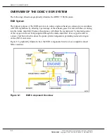
Page 102: ...e manifold Engine exhaust gases will dilute the incoming air by displacing some of the oxygen in the air being supplied through the intake manifold Less oxygen results in a slower fuel burn which reduces the peak cylinder temperature permitting reduced nitrogen oxides NOx emissions Figure 8 1 graphically illustrates how the EGR components function to accomplish reduced NOx emissions Figure 8 1 EGR...

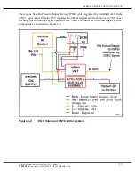
Page 103: ... regulates the VPOD air pressure which allows the VNT vanes to change position during engine operation The VPOD also interfaces with other engine system components as illustrated in Figure 8 2 Figure 8 2 EGR Valve and VNT Control System All information subject to change without notice Rev June 2005 8 3 7SE60 0506 Copyright 2005 DETROIT DIESEL CORPORATION ...

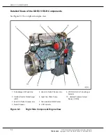
Page 104: ...ut to Turbocharger Actuator 2 Variable Nozzle Turbocharger VNT 6 High Flow Water Pump 10 Variable Pressure Output Device VPOD 3 Venturi to Delta P Sensor Line 7 Tube and Shell EGR Cooler 4 Delta P Sensor 8 VNT Actuator Figure 8 3 Right Side Component Engine View 8 4 All information subject to change without notice Rev June 2005 7SE60 0506 Copyright 2005 DETROIT DIESEL CORPORATION ...

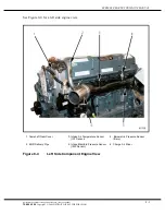
Page 105: ...r Temperature Sensor IAT Sensor 5 Barometric Pressure Sensor Baro 2 EGR Delivery Pipe 4 Intake Manifold Pressure Sensor IMP Sensor 6 Charge Air Mixer Figure 8 4 Left Side Component Engine View All information subject to change without notice Rev June 2005 8 5 7SE60 0506 Copyright 2005 DETROIT DIESEL CORPORATION ...

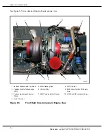
Page 106: ...e Nozzle Turbocharger VNT 6 Venturi Tube 9 EGR Valve Control Oil Supply Line 3 Turbocharger Speed Sensor TSS 7 EGR Tube and Shell Cooler 10 VPOD to VNT Actuator Air Line 4 Delta P Sensor Figure 8 5 Front Right Side Component Engine View 8 6 All information subject to change without notice Rev June 2005 7SE60 0506 Copyright 2005 DETROIT DIESEL CORPORATION ...

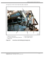
Page 107: ...Pressure Sensor 4 Engine Oil Pressure Sensor 2 Check Valve and Regulator Fitting for Return Fuel 5 Injector Harness Connector 3 Breather Tube Figure 8 6 Lower Rear Left Side Engine Components All information subject to change without notice Rev June 2005 8 7 7SE60 0506 Copyright 2005 DETROIT DIESEL CORPORATION ...

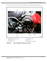
Page 108: ...7 a detailed view of the Delta P Sensor 1 Thermostat Housing 2 Delta P Sensor Figure 8 7 Delta P Sensor Location 8 8 All information subject to change without notice Rev June 2005 7SE60 0506 Copyright 2005 DETROIT DIESEL CORPORATION ...

Page 109: ...ocation 1 EGR Control Valve Oil Supply Line 4 Delta P Sensor Lines 2 VNT Actuator Air Line 5 EGR Valve 3 VNT Actuator 6 EGR Valve Hydraulic Actuator Figure 8 8 VNT and Related Components Location All information subject to change without notice Rev June 2005 8 9 7SE60 0506 Copyright 2005 DETROIT DIESEL CORPORATION ...

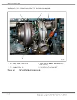
Page 110: ...er Speed Sensor TSS 3 Turbocharger Compressor Outlet Temperature Sensor TCOT 2 Turbocharger Oil Inlet Line 4 Variable Nozzle Turbocharger VNT Figure 8 9 VNT and Related Components 8 10 All information subject to change without notice Rev June 2005 7SE60 0506 Copyright 2005 DETROIT DIESEL CORPORATION ...

Page 111: ... Fey ring exhaust manifold 1 Fey Ring Grooves with Fey Rings 3 Exhaust Manifold Assembly 2 EGR Valve to Bellow Connector Figure 8 10 Fey Ring Exhaust Manifold All information subject to change without notice Rev June 2005 8 11 7SE60 0506 Copyright 2005 DETROIT DIESEL CORPORATION ...

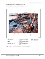
Page 112: ... diagnostic checks of RPM load altitude air temperature etc and uses this information to determine the valve position When the EGR valve is closed exhaust gas will flow from the exhaust manifold or through the turbine wheel in the turbocharger and out the exhaust system When the EGR valve is open some of the exhaust gas is directed into the EGR cooler through the delivery pipe and into the intake ...

Page 113: ...rol Valve Hydraulic Actuator 7 Exhaust Manifold Center Housing to Bellow Pipe 2 Bellows 5 EGR Control Valve Oil Return Connector 3 EGR Control Valve Body 6 EGR Control Valve Oil Supply Line Figure 8 12 Top Right Side View of EGR Components All information subject to change without notice Rev June 2005 8 13 7SE60 0506 Copyright 2005 DETROIT DIESEL CORPORATION ...

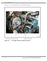
Page 114: ...ew of the EGR components 1 EGR Control Valve Hydraulic Actuator 2 Delivery Pipe Connection Figure 8 13 Front Right Side View of EGR Components 8 14 All information subject to change without notice Rev June 2005 7SE60 0506 Copyright 2005 DETROIT DIESEL CORPORATION ...

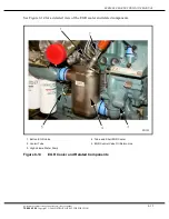
Page 115: ...components 1 Bolt on EGR Valve 4 Tube and Shell EGR Cooler 2 Venturi Tube 5 EGR Control Valve Oil Return Line 3 High Volume Water Pump Figure 8 14 EGR Cooler and Related Components All information subject to change without notice Rev June 2005 8 15 7SE60 0506 Copyright 2005 DETROIT DIESEL CORPORATION ...

Page 116: ...rating modes A DDEC equipped engine is built with an electronically controlled fuel injection system which eliminates control racks or mechanical linkages requiring periodic adjust Fuel economy and vehicle performance are also improved during cold starting and the increased initial idle speed allows for fast engine warm up Horsepower torque idle and engine speed are managed by the ECU Such functio...

Page 117: ...essor Inlet Temperature Sensor The Turbocharger Compressor Inlet Temperature Sensor TCI sensor is installed by the OEM within piping between the air filter and the turbocharger inlet The TCI sensor along with other DDEC sensors are monitored by the ECU as a means of fuel management during normal operation The TCI sensor is supplied a 5 volt signal from the ECU and returns a voltage signal to the E...

Page 118: ...or to monitor the pressure differential across the venturi as EGR exhaust gases flow through the EGR delivery pipe to the charge air mixer DDEC V uses this information along with temperature and density of the exhaust gases to determine precise EGR Mass Flow Rate Figure 8 16 Venturi Tube 8 18 All information subject to change without notice Rev June 2005 7SE60 0506 Copyright 2005 DETROIT DIESEL CO...

Page 119: ...flow of exhaust gases through the EGR cooler tubes The EGR cooler core then transfers the heat removed from the exhaust gases to the engine coolant The cooled exhaust gases are then mixed with incoming air from the charge air cooler before being sent to the intake manifold Figure 8 17 EGR Cooler All information subject to change without notice Rev June 2005 8 19 7SE60 0506 Copyright 2005 DETROIT D...

Page 120: ...nt of the cooling system radiator and is connected to the turbocharger and intake manifold which permits a more dense charge of air to be delivered to the engine The compressed air leaving the turbocharger is directed through the CAC before it flows into the CAC to be mixed with EGR exhaust gases before entering the intake manifold Cooling is accomplished by incoming air flowing past the tubes and...

Page 121: ...r connects via a rod to the pin joint of the turbine external arm Rotation of the external arm simultaneously rotates several pivoting nozzle vanes positioned inside the turbine housing at the outer periphery of the turbine wheel This adjusts turbocharger speed boost and EGR flow in accordance with DDEC engine management control NOTE VNT actuator is spring loaded If air pressure is lost the actuat...

Page 122: ...DDEC V COMPONENTS Figure 8 20 VNT Actuator 8 22 All information subject to change without notice Rev June 2005 7SE60 0506 Copyright 2005 DETROIT DIESEL CORPORATION ...

Page 123: ...o system components are required for proper operation of the EGR valve and the VNT control system Ƒ 12V or 24V Power Supply Ƒ DDEC V ECU PWM 3 E1 EGR and PWM 4 E4 VNT NOTE VNT is fully open at 7 and closed at 90 Figure 8 21 EGR Valve and VNT Control System All information subject to change without notice Rev June 2005 8 23 7SE60 0506 Copyright 2005 DETROIT DIESEL CORPORATION ...

Page 124: ...termine the EGR valve position The ECU changes the EGR valve position via a PWM to the solenoid in the actuator See Figure 8 22 NOTE When installing a new hydraulic actuator or EGR valve manually closing the valve during installation will make the first start up easier Once the engine has started and oil pressure through the actuator has equalized operation will be normal The EGR valve operating v...

Page 125: ...sensor is supplied a 5 volt reference signal from the ECU and returns a voltage signal to the ECU relative to exhaust gas temperatures in the EGR delivery pipe The sensor return voltage decreases as exhaust gas temperature increases sensor operating values are 0 10 5 0 V See Figure 8 23 to view the sensor with connector Figure 8 23 EGR Tempertaure Sensor All information subject to change without n...

Page 126: ...e sensor is supplied a 5 volt reference signal from the ECU and returns a voltage signal to ECU relative to pressure difference across the Venturi tube Return sensor voltage increases as pressure differential increases during engine operation operating values are 0 23 4 77 V 1 Thermostat Housing 2 Delta P Sensor Figure 8 24 Delta P Sensor 8 26 All information subject to change without notice Rev J...

Page 127: ...ent during engine acceleration The IMP Sensor sensor is supplied a 5 volt reference signal by ECU and returns a voltage signal to the ECU relative to turbo boost pressure Return voltage increases as boost pressure increases Operating values are 0 10 5 0 V during normal engine operation Figure 8 25 Turbocharger Boost Sensor All information subject to change without notice Rev June 2005 8 27 7SE60 0...

Page 128: ...DDEC V COMPONENTS THIS PAGE INTENTIONALLY LEFT BLANK 8 28 All information subject to change without notice Rev June 2005 7SE60 0506 Copyright 2005 DETROIT DIESEL CORPORATION ...

Page 129: ...l Sensor Input Voltage Low 13 146 6 EGR Valve Current Too High 14 110 3 Coolant Temperature Sensor Input Voltage High 14 175 3 Oil Temperature Sensor Input Voltage High 15 110 4 Coolant Temperature Sensor Input Voltage Low 15 175 4 Oil Temperature Sensor Input Voltage Low 16 111 3 Coolant Level Sensor Input Voltage High 16 111 5 Add Coolant Level Sensor Input Voltage High 16 146 5 EGR Valve Curren...

Page 130: ...261 3 Aux Output 13 E47 Open Circuit High Side 31 261 4 Aux Output 13 E47 Short To Ground High Side 31 261 7 Aux Output 13 E47 Mechanical System Failure 31 262 3 Aux Output 14 E50 Open Circuit High Side 31 262 4 Aux Output 14 E50 Short To Ground High Side 31 262 7 Aux Output 14 E50 Mechanical System Failure High Side 31 263 3 Aux Output 15 E51 Open Circuit High Side 31 263 4 Aux Output 15 E51 Shor...

Page 131: ...Intake Manifold Temperature High 44 105 14 Engine Power Derate Due To Intake Manifold Temperature 44 110 0 Coolant Temperature High 44 110 14 Engine Power Derate Due To Coolant Temperature 44 172 0 Air Inlet Temperature High 44 175 0 Oil Temperature High 44 175 14 Oil Temperature Derate 45 100 1 Oil Pressure Low 46 155 4 Injector Vreg Voltage Failed Low 46 168 1 ECU Battery Voltage Low 46 211 1 Ve...

Page 132: ...sponding 58 70 12 Park Brake Safety Loop Switch Failed 58 92 0 Torque Overload 58 216 7 ECU Information Not Responding Mux d Dashboard Devices 58 242 9 Cruise Control Resume Accel Switch Not Responding 58 242 12 Cruise Control Resume Accel Switch Failed 58 243 9 Cruise Control Set Coast Switch Not Responding 58 243 12 Cruise Control Set Coast Switch Failed 58 244 9 Cruise Control Enable Switch Not...

Page 133: ...pen Circuit V53 62 56 7 Aux Output 8 Mechanical System Not Responding Properly V53 62 250 12 J1587 Data Link Fault 62 257 3 Aux Output 9 V54 Short To Battery 62 257 4 Aux Output 9 V54 Open Circuit 62 257 7 Aux Output 9 V54 Mechanical System Failure Pin Top 2 62 258 3 Aux Output 10 V55 Short To Battery 62 258 4 Aux Output 10 V55 Open Circuit 62 258 7 Aux Output 10 V55 Mechanical System Failure Top ...

Page 134: ...bo Speed Sensor Input Failure Abnormal Period 65 107 3 Air Filter Restriction Sensor Voltage High 65 107 4 Air Filter Restriction Sensor Voltage Low 66 99 3 Oil Filter Restriction Sensor Voltage High 66 99 4 Oil Filter Restriction Sensor Voltage Low 67 106 3 Air Inlet Pressure Sensor Input Voltage High 67 106 4 Air Inlet Pressure Sensor Input Voltage Low 67 109 3 Coolant Pressure Circuit Failed Hi...

Page 135: ...Air filter Restriction Pressure Low 77 108 0 Barometric Pressure High 77 108 1 Barometric Pressure Low 77 109 0 Coolant Pressure High 77 110 1 Coolant Temperature Low 77 111 0 Coolant Level High 77 151 11 Service Now Lamp Fault Expiration 77 171 0 Ambient Air Temperature High 77 171 1 Ambient Air Temperature Low 77 172 1 Air Inlet Temperature Low 77 174 0 Fuel Temperature High 77 174 1 Fuel Temper...

Page 136: ...Now 83 411 0 EGR Delta Pressure High 83 412 0 EGR Temperature High 84 98 1 Oil Level Low 84 355 1 Change Oil Soon 85 190 0 Engine Overspeed 85 190 14 Engine Overspeed Signal 86 73 3 Aux Pump Pressure Sensor Input Voltage High 86 108 3 Barometric Pressure Sensor Input Voltage High 87 73 4 Pump Pressure Sensor Input Voltage Low 87 108 4 Barometric Pressure Sensor Input Voltage Low 89 95 0 Fuel Filte...

Page 137: ... pins A and B See Figure 9 1 for pin locations and compare the measured ohm values to the ohm values listed in Table 9 29 2 a If the coil resistance is too low replace the actuator assembly b If the coil resistance is acceptable go to step 4 4 Disconnect engine harness at ECU and at coil and measure resistance across the two pin connector pins a If resistance is less than 100 the two wires are sho...

Page 138: ...ed to ground Ƒ Low resistance in the solenoid NOTE This symptom may be improved with reprogramming Reprogram the ECU if the ECU has not been reprogrammed since the dates listed below Ƒ 12 L 02 23 04 Ƒ 14 L 03 08 04 NOTE There is an update program for the DDEC V troubleshooting in 6 0 DDDL 9 10 All information subject to change without notice Rev June 2005 7SE60 0506 Copyright 2005 DETROIT DIESEL C...

Page 139: ... 6 EGR valve electric current is too low FMI 5 or EGR valve electric current is too high FMI 6 The CEL AWL will be illuminated and the engine will operate in boost mode All information subject to change without notice Rev June 2005 9 11 7SE60 0506 Copyright 2005 DETROIT DIESEL CORPORATION ...

Page 140: ...DDEC V CODES THIS PAGE INTENTIONALLY LEFT BLANK 9 12 All information subject to change without notice Rev June 2005 7SE60 0506 Copyright 2005 DETROIT DIESEL CORPORATION ...

Page 141: ...sues Ƒ Slobbering from Exhaust Pipe Ƒ Poor Engine Performance Ƒ Cab Odors Ƒ Loss of Engine Coolant TESTING PROCEDURES The following testing procedures are based on conditions identified by the Detroit Diesel Customer Support Center Ƒ Test A go to page 10 10 Ƒ Test B go to page 10 12 Ƒ Test C go to page 10 13 Ƒ Test D go to page 10 20 Ƒ Test E go to page 10 20 Ƒ Test F go to page 10 21 Ƒ Test G go ...

Page 142: ...upport Center at 313 592 5800 b If Flash Code 13 SID 146 FMI 6 is not logged troubleshooting task is complete FLASH CODE 16 SID 146 FMI5 EGR VALVE CURRENT TOO LOW Troubleshooting steps are as follows 1 Using DDDL check for Flash Code 16 SID 146 FMI 5 a If Flash Code 16 SID 146 FMI 5 was logged perform TEST E b If Flash Code 16 SID 111 FMI 5 was logged refer to the proper code section of the DDEC V...

Page 143: ...f Flash Code 61 was logged perform step 2 b If Flash Code 61 was not logged no further troubleshooting is required 2 Verify that Modification Bulletin 05M 2 Series 60 EPA 04 Fuel System have been performed a If the procedures in Modification Bulletin 05M 2 Series 60 EPA 04 Fuel System have not been performed do so now To print a copy of 05M 2 please visit the Detroit Diesel Modification Letter Web...

Page 144: ...ection TEST A 6 Once service is done verify that the problem has been resolved BLACK FUEL Troubleshooting steps are as follows 1 Visually inspect the fuel tank for black fuel a If black fuel is present in the fuel tank perform step 2 b If black fuel is not present in the fuel tank no further troubleshooting is required 2 Verify that Modification Bulletin 05M 2 Series 60 EPA 04 Fuel System have bee...

Page 145: ...g is required 2 Verify that Modification Bulletin 05M 2 Series 60 EPA 04 Fuel System have been performed a If the procedures in Modification Bulletin 05M 2 Series 60 EPA 04 Fuel System have not been performed do so now To print a copy of 05M 2 please visit the Detroit Diesel Modification Letter Web Page at http 192 135 85 10 cust mods 05mods Index05 asp b If the procedures in Modification Bulletin...

Page 146: ...fuel injectors are leaking fuel Refer to the N3 Electronic Unit Injector section of the Series 60 Service Manual 6SE483 for removal inspection and replacement steps 4 Verify valve lash clearances Refer to section Valve Clearance and Injector Timing section of the Series 60 Service Manual 6SE483 for inspection steps 5 Check for worn cylinders a Perform a crankcase pressure test Refer to the proper ...

Page 147: ...t blocked filter elements and damage Refer to the Air Cleaner section of the Series 60 Service Manual 6SE483 for removal inspection and installation steps 5 Verify that the VPOD is connected to a dedicated air line a If the VPOD air line is not connected to a dedicated source refer to OEM guidelines for a solution Once the problem has been resolved proceed to step 6 b If the VPOD air line is conne...

Page 148: ...aust manifold for damage and exhaust gas leaks Refer to the Exhaust Manifold section of the Series 60 Service Manual 6SE483 for inspection steps a If damage was found resolve the problems and proceed to step 3 b If no damage was found proceed to step 3 3 Verify repairs have resolved the cab odor problem a If cab odor problems have not been resolved please contact the Detroit Diesel Customer Suppor...

Page 149: ...he coolant hoses are worn broken and damaged Refer to the proper service sections of the Series 60 Service Manual 6SE483 for repair procedures Once the problems have been resolved proceed to step 4 b If the coolant hoses are not worn broken and damaged proceed to step 4 4 Visually inspect the cylinder head to cylinder block for coolant leaks a If cylinder head to cylinder block coolant leaks were ...

Page 150: ...or equivalent 3 Using DDDL monitor the boost pressure psi a If the pressure is below 187 kPa 27 psi visually inspect the CAC hoses and the delivery tube for leaks Repair as necessary b If the pressure is 187 kPa 27 psi or higher continue to step 4 4 Disconnect the EGR actuator oil line NOTE The oil line fitting is a 37 degree JIC 6 fitting 5 Connect a regulated air supply line to the EGR actuator ...

Page 151: ...p 10 8 Physically inspect the EGR valve for a mechanical failure If the EGR valve is not functioning correctly replace the EGR valve 9 Visually inspect the EGR cooler for restrictions If the EGR cooler is restricted replace the EGR cooler 10 Visually check the delivery pipe for restrictions Clean the pipe as necessary to remove restrictions 11 Verify repairs All information subject to change witho...

Page 152: ...vailable run the engine until hot 170 F 76 C coolant temperature 2 Activate the VPOD outputs to 50 duty cycle using the DDDL Visually inspect the VNT and EGR valve for proper rod travel a If the VNT is not functioning properly please visit the Detroit Diesel Technical Service Letter Web Page at http 192 135 85 10 cust sletr revised_2004 asp and browse for Technical Service Letter 04 TS 16 or Detro...

Page 153: ...upply Voltage Ƒ VPOD Wiring Ƒ Active Codes Ƒ Final Test The following tools are required to perform the six basic tests Ƒ Low wattage 1 000 resistor Ƒ DDDL version 4 2 or higher or DDR suite 8 Ƒ Volt Ohm Meter VOM Ƒ Pressure gage 1379 kPa 0 200 psi Ƒ Pressure gage 690 kPa 0 100 psi All information subject to change without notice Rev June 2005 10 13 7SE60 0506 Copyright 2005 DETROIT DIESEL CORPORA...

Page 154: ...ecessary verify repairs If no problem was found proceed to step 3 b NOTE Reversed and damaged tubes and Venturi ports will have an adverse effect on engine performance resulting in black exhaust smoke and engine surging b If the recorded Delta P counts are 86 135 visually inspect the delivery pipe for damage and proper assembly If no damage or improper assembly were detected perform a VPOD Output ...

Page 155: ...he VNT actuator See Figure 10 1 Figure 10 1 Location of Venturi Tube Hoses 2 Install gage at the outlet of the VNT air line See Figure 10 2 NOTE The gage should be accurate to within 1 4 kPa 0 2 psi All information subject to change without notice Rev June 2005 10 15 7SE60 0506 Copyright 2005 DETROIT DIESEL CORPORATION ...

Page 156: ...avel 4 Repeat step 3 a total of 3 times NOTICE Ensure that the VPOD air supply line fitting is not crossed thread when connecting the VPOD air supply to the EGR actuator If the air supply line fitting is not properly seated the EGR actuator will not function properly 5 Connect VPOD air supply line to the EGR actuator Perform a VPOD Input Pressure Test 10 16 All information subject to change withou...

Page 157: ...ltage 1 Check VPOD label to determine if it is 12 V or 24 V system NOTE A 1 000 resistor or a volt Ohm meter is required to perform step 2 2 Unplug the VPOD wire connectors and insert the 1 000 resistor between cavities 1 and 3 a Turn ignition switch ON b Measure voltage from pin 3 to pin 1 c Plug in DDDL or DDR to measure the ECU voltage 3 Is the VPOD part number and voltage and the ECU voltage c...

Page 158: ...OD or pin Number 2 and pin Number 1 for a 24 V VPOD 5 Using either a DDDL or DDR activate the PWM 4 VNT and ensure that activating 50 duty cycle VDC 50 of the VPOD supply voltage 1 volt e g voltage to VPOD 13 8 V 0 5 6 8 V therefore 5 8 V to 7 8 V at VPOD is okay 6 Listen for air leaks from the VPOD when PWM are activated to 50 a If the PWM voltage measurement is correct go to step 7 b If the PWM ...

Page 159: ...as a power loss it could be explained that loss of power was done by the ECU to protect other engine components 5 If the issue is not related to the EGR system components or if technical support is required contact the Detroit Diesel Customer Support Center at 313 592 5800 6 Perform a Final Test Final Test Follow these steps for a final test 1 Reconnect all disconnected sensors and wiring harnesse...

Page 160: ...nce is less than 4 1 kPa 0 6 psi contact the Detroit Diesel Customer Support Center at 313 592 5800 3 Verify repair a If Flash Code 39 SID 147 FMI 2 is not logged repair is complete b If Flash Code 39 SID 147 FMI 2 is logged contact the Detroit Diesel Customer Support Center at 313 592 5800 TEST E Test E steps are as follows 1 Verify ECU program software version a If the ECU software version is no...

Page 161: ... responsible for the loss of engine coolant NOTE Coolers with internal leaks usually show signs of a white coolant drop out at the exhaust side of the cooler the Delta P Sensor lines or at the delivery pipe to intake manifold connector If the entire system has been tested perform the following steps to inspect the cooler 1 Use hoses clamps plugs and a regulator to seal the cooler water inlet and w...

Page 162: ...tor and watch for bubbles on the exhaust side of the cooler See Figure 10 5 a If bubbles were observed replace the cooler b If no bubbles were observed contact the Detroit Diesel Customer Support Center for further information 313 592 5800 Figure 10 5 Observing the EGR Cooler for Bubbles 10 22 All information subject to change without notice Rev June 2005 7SE60 0506 Copyright 2005 DETROIT DIESEL C...

Page 163: ...ir supply line is a dedicated air supply line please read Freightliner Service Information Bulletin 01 81 see Figure 10 6 see Figure 10 7 and see Figure 10 8 Figure 10 6 Freightliner Service Bulletin 01 81 Page One of Three All information subject to change without notice Rev June 2005 10 23 7SE60 0506 Copyright 2005 DETROIT DIESEL CORPORATION ...

Page 164: ...DDEC V TESTING Figure 10 7 Freightliner Service Bulletin 01 81 Page Two of Three 10 24 All information subject to change without notice Rev June 2005 7SE60 0506 Copyright 2005 DETROIT DIESEL CORPORATION ...

Page 165: ...GR TECHNICIAN S MANUAL Figure 10 8 Freightliner Service Bulletin 01 81 Page Three of Three All information subject to change without notice Rev June 2005 10 25 7SE60 0506 Copyright 2005 DETROIT DIESEL CORPORATION ...

Page 166: ...DDEC V TESTING THIS PAGE INTENTIONALLY LEFT BLANK 10 26 All information subject to change without notice Rev June 2005 7SE60 0506 Copyright 2005 DETROIT DIESEL CORPORATION ...

Page 167: ...SH Engine Harness EH Fire Truck Pump Pressure Sensor Fire Truck Pump Pressure Sensor Fuel Restriction Sensor FRS Fuel Restriction Sensor Fuel Temperature Sensor FTS Supply Fuel Temperature Sensor SFT Sensor Limiting Speed Governor LSG Automotive Limiting Speed Governor ALSG Oil Level Sensor OLS Engine Oil Level EOL Sensor Oil Pressure Sensor OPS Engine Oil Pressure Sensor EOP Sensor Oil Temperatur...

Page 168: ...APPENDIX A LIST OF ACRONYMS A 2 All information subject to change without notice Rev June 2005 7SE60 0506 Copyright 2005 DETROIT DIESEL CORPORATION ...

Page 169: ...WIRING SCHEMATICS Ƒ DDEC IV Vehicle Harness Ƒ DDEC IV Engine Wiring Diagram Ƒ DDEC V Engine Harness Ƒ DDEC V Vehicle Interface Harness All information subject to change without notice Rev June 2005 B 1 7SE60 0506 Copyright 2005 DETROIT DIESEL CORPORATION ...

Page 170: ...APPENDIX B DDEC IV WIRING SCHEMATICS B 2 All information subject to change without notice Rev June 2005 7SE60 0506 Copyright 2005 DETROIT DIESEL CORPORATION ...

Page 171: ......

Page 172: ......

Page 173: ......

Page 174: ......

Page 175: ...TECHNICIAN S MANUAL APPENDIX C ENGINE DIAGNOSTIC QUESTIONNAIRE Ƒ Engine Diagnostic Questionnaire All information subject to change without notice Rev June 2005 C 1 7SE60 0506 Copyright 2005 DETROIT DIESEL CORPORATION ...

Page 176: ...APPENDIX C ENGINE DIAGNOSTIC QUESTIONNAIRE C 2 All information subject to change without notice Rev June 2005 7SE60 0506 Copyright 2005 DETROIT DIESEL CORPORATION ...

Page 177: ......

Page 178: ...Service Letter 03 TS 44 Ƒ Technical Service Letter 03 TS 44 Ƒ Technical Service Letter 03 TS 44 Ƒ Technical Service Letter 04 TS 17 Ƒ Technical Service Letter 04 TS 16 Ƒ Technical Service Letter 04 TS 16 Ƒ Technical Service Letter 04 TS 16 Ƒ Technical Service Letter 04 TS 16 All information subject to change without notice Rev June 2005 D 1 7SE60 0506 Copyright 2005 DETROIT DIESEL CORPORATION ...

Page 179: ......

Page 180: ......

Page 181: ......

Page 182: ......

Page 183: ......

Page 184: ......

Page 185: ......

Page 186: ......

Page 187: ......

Page 188: ......

Page 189: ......

Page 190: ...ECM Engine Harness Connector View see Figure E 2 Ƒ Engine Harness Connector Pin Locations see Figure E 3 Ƒ Vehicle Interface Harness Connector see Figure E 4 Ƒ Vehicle Interface Harness Connector Pin Locations see Figure E 5 All information subject to change without notice Rev June 2005 E 1 7SE60 0506 Copyright 2005 DETROIT DIESEL CORPORATION ...

Page 191: ...E DDEC IV ECM OVERVIEW AND VEHICLE INTERFACE HARNESS Figure E 1 DDEC IV ECM Front Side View E 2 All information subject to change without notice Rev June 2005 7SE60 0506 Copyright 2005 DETROIT DIESEL CORPORATION ...

Page 192: ...SERIES 60 EGR TECHNICIAN S MANUAL Figure E 2 ECM Engine Harness Connector View All information subject to change without notice Rev June 2005 E 3 7SE60 0506 Copyright 2005 DETROIT DIESEL CORPORATION ...

Page 193: ... IV ECM OVERVIEW AND VEHICLE INTERFACE HARNESS Figure E 3 Engine Harness Connector Pin Locations E 4 All information subject to change without notice Rev June 2005 7SE60 0506 Copyright 2005 DETROIT DIESEL CORPORATION ...

Page 194: ...SERIES 60 EGR TECHNICIAN S MANUAL Figure E 4 Vehicle Interface Harness Connector All information subject to change without notice Rev June 2005 E 5 7SE60 0506 Copyright 2005 DETROIT DIESEL CORPORATION ...

Page 195: ...CM OVERVIEW AND VEHICLE INTERFACE HARNESS Figure E 5 Vehicle Interface Harness Connector Pin Locations E 6 All information subject to change without notice Rev June 2005 7SE60 0506 Copyright 2005 DETROIT DIESEL CORPORATION ...

Reviews: