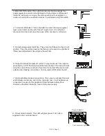
3: Main ON-OFF switch. This switch can be used to de-energize the
power supply for service and adjustments. High voltage is still present
inside the enclosure as long as the main power feed is energized, so
caution should still be used when service is performed using this switch.
4: 1 Amp circuit breaker. This is intended to protect the device against
high current loads and is part of the AC input circuit. It is a thermal
device and can be reset once the cause of the overload is corrected.
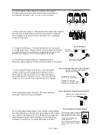
5: Output voltage select switches. These must both be set to the 24 volt
position. They should be preset at the factory and require no adjustment.
If they need adjustment, de-energize the unit first.
6: Output terminals. Outputs 24 volts at 1 amp maximum. The output is
protected by a PTC thermally resetable fuse element. The fuse will reset
once the cause of the overload is found and corrected. Observe correct
polarity when making connections. Factory wired to ER control board.
7: Optional battery backup connections. This output is intended for lead
acid batteries and is also at 24 volts. Typically, two 12 volt batteries are
connected in series for this application. Approximate battery life is
charted on the label inside the cover of the power supply.
Power Indicator
Green when power is good
8: Power Good Indicator. This LED will glow green if 24 volts is
supplied to the controller board.
101339 Page 3


