


11
FIGURE 2-9
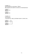
RTD Input
Make RTD connections as illustrated below. For a three wire RTD, connect the
resistive leg of the RTD to terminal 6 and the common legs to terminals 4 and 5. For a
two wire RTD, connect one leg to terminal 5 and the other leg to terminal 6 as shown
below. A jumper wire supplied by the customer must be installed between terminals 4
and 5. Input conditioning jumper must be positioned correctly (see Appendix A) and
Hardware Definition Code must be correct (see Appendix B).
FIGURE 2-10
Volt, mV Input
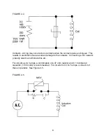
Make volt and millivolt connections as shown below. Terminal 5 is positive and
terminal 4 is negative. Input conditioning jumper must be positioned correctly (see
Appendix A) and Hardware Definition Code must be correct (see Appendix B).
mADC Input
Make mADC connections as shown below. Terminal 4 is positive and terminal 6 is
negative. Input conditioning jumper must be positioned correctly (see Appendix A) and
Hardware Definition Code must be correct (see Appendix B).
Summary of Contents for MIC 1162
Page 2: ......
Page 4: ...ii...
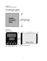
Page 8: ...4 FIGURE 2 1 Panel Cut Out Dimensions FIGURE 2 2 Main Dimensions...
Page 26: ...22...
Page 30: ...26...
Page 34: ...30...
Page 36: ...32...
Page 40: ...36...
Page 41: ...37 APPENDIX A BOARD LAYOUT JUMPER POSITIONING FIGURE A 1 Exploded View Board Layout...
Page 42: ...38 FIGURE A 2 CPU PWA...
Page 43: ...39 FIGURE A 3 OPTION PWA DC OUTPUT 2 OUTPUT 3...
Page 44: ...40...
Page 48: ...44...
Page 54: ...50...


