background image

112126-01B

For more information, visit www.desatech.com

For more information, visit www.desatech.com

20

 CAUTION: Use only new, black iron or steel pipe.

Internally-tinned copper tubing may be used in cer-
tain areas. Check your local codes. Use pipe of 1/2"
diameter or greater to allow proper gas volume to
burner system. If pipe is too small, undue loss of
volume will occur.

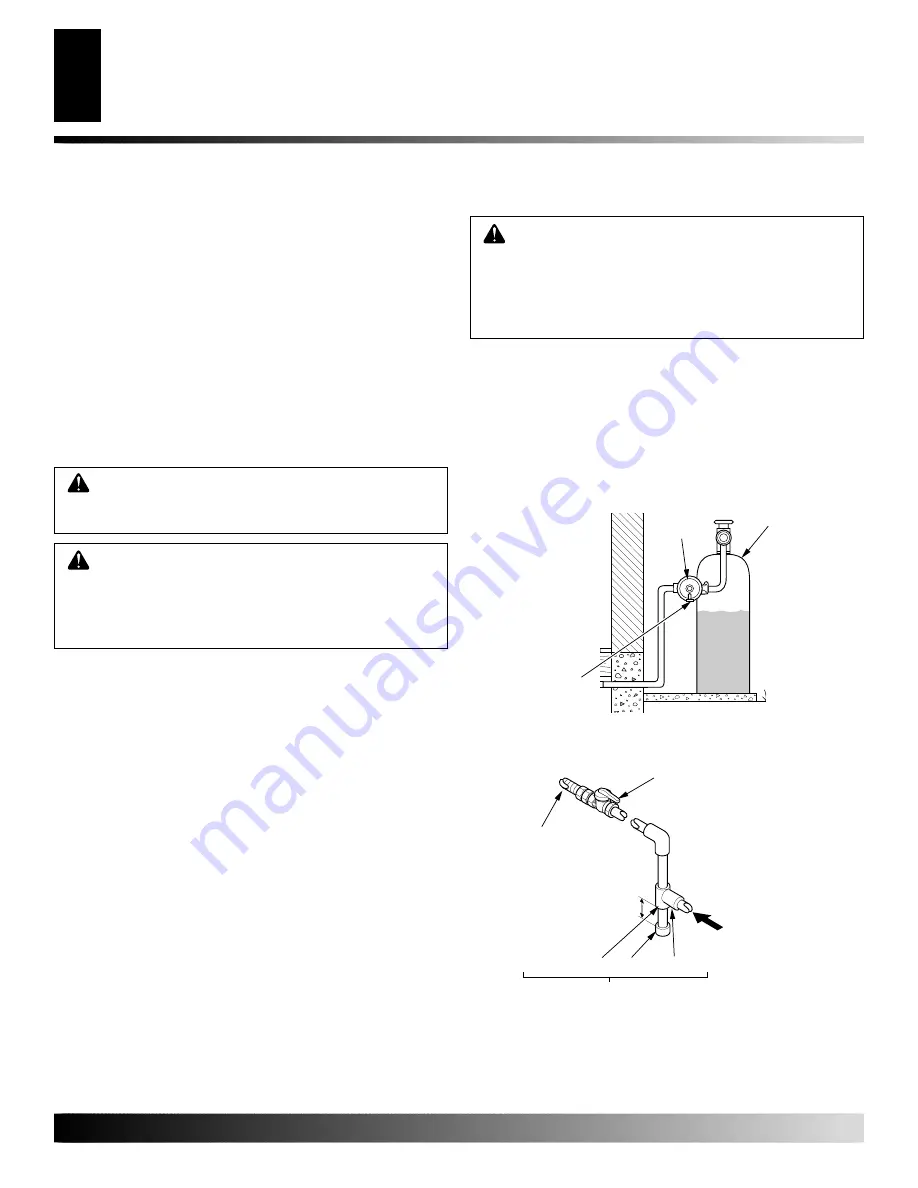
Installation must include an equipment shutoff valve, union, and
plugged 1/8" NPT tap. Locate NPT tap within reach for test gauge hook
up. NPT tap must be upstream from burner system (see Figure 40).

IMPORTANT:

 Install main gas valve (equipment shutoff valve) in

an accessible location. The main gas valve is for turning on and
shutting off the gas to the appliance.

Check your building codes for any special requirements for locating
equipment shutoff valve to stoves.

STOVE AND DIRECT-VENT
BURNER SYSTEM
INSTALLATION

INSTALLING GAS PIPING TO STOVE/
BURNER SYSTEM LOCATION

Installation Items Needed

Before installing stove and burner system, make sure you have the
items listed below.
• external regulator (supplied by installer)
• piping (check local codes)
• sealant (resistant to propane/LP gas)
• equipment shutoff valve *
• test gauge connection *
• sediment trap
• tee joint
• pipe wrench
• approved flexible gas line with gas connector (if allowed by lo-

cal codes) (not provided)

* A CSA design-certified equipment shutoff valve with 1/8" NPT tap
is an acceptable alternative to test gauge connection. Purchase the
CSA design-certified equipment shutoff valve from your dealer.

For propane/LP connections only, the installer must supply an
external regulator. The external regulator will reduce incoming gas
pressure. You must reduce incoming gas pressure to between 11 and
14 inches of water. If you do not reduce incoming gas pressure,
burner system regulator damage could occur. Install external regu-
lator with the vent pointing down as shown in Figure 39. Pointing
the vent down protects it from freezing rain or sleet.

 WARNING: A qualified installer or service person

must connect burner system to gas supply. Follow all
local codes.

 CAUTION: For propane/LP units, never connect

burner system directly to the propane/LP supply. This
burner system requires an external regulator (not
supplied). Install the external regulator between the
burner system and propane/LP supply.

Figure 39 - External Regulator with Vent Pointing Down
(Propane/LP Only)

Propane/LP
Supply Tank

External
Regulator

Vent Pointing
Down

CHECK GAS TYPE

Use proper gas type for the burner system unit you are installing. If
you have conflicting gas types, do not install burner system. See
dealer where you purchased the stove and burner system for proper
burner system according to your gas type. Conversion kits are also
available for these models, see 

Accessories

 on page 38.

IMPORTANT:

 If installing gas conversion kit, do so at this time.

Be sure to follow all installation instructions included with
conversion kit.

Figure 40 - Gas Connection

* The CSA design-certified equipment shutoff valve may be sup-
plied with the appliance or you can purchase it from your dealer.

CSA Design-Certified
Equipment Shutoff Valve with
1/8" NPT Tap*

3" Minimum

Approved Flexible
Gas Line

 Pipe Nipple  Cap  Tee Joint

Sediment Trap/Drip Leg

Propane/LP

 - From

External Regulator
(11" W.C. to 14" W.C.
Pressure)

Natural 

- From Gas

Meter (5" W.C. to
10.5" W.C. Pressure)

STOVE AND DIRECT-VENT BURNER SYSTEM INSTALLATION

Check Gas Type
Installing Gas Piping to Stove/Burner System Location

Summary of Contents for SDVBND

Page 1: ...r flammable vapors and liquids in the vicinity of this or any other appliance Installation and service must be performed by a qualified installer service agency or the gas supplier IMPORTANT This direct vent burner system must be installed into approved cast iron stove bodies models SCIVFC PSCIVFC VCIS PVCIS VH series ONLY This appliance may be installed in an aftermarket permanently located manuf...

Page 2: ...ION PREPARATION 4 CAST IRON STOVE AND DIRECT VENT BURNER SYSTEM ASSEMBLY 5 GENERAL VENTING 10 VENTING INSTALLATION 12 STOVE AND DIRECT VENT BURNER SYSTEM INSTALLATION 20 OPERATING STOVE WITH BURNER SYSTEM 26 INSPECTING BURNERS 28 CLEANING AND MAINTENANCE 29 TROUBLESHOOTING 30 SPECIFICATIONS 33 WIRING DIAGRAM 33 REPLACEMENT PARTS 33 ILLUSTRATED PARTS BREAKDOWN AND PARTS LIST 34 TECHNICAL SERVICE 38...

Page 3: ...nance page 29 11 Keep the area around your stove clear of combustible materi als gasoline and other flammable vapor and liquids Do not run burner system where these are used or stored Do not place items such as clothing or decorations on or around stove 12 Do not use this stove to cook food or burn paper or other objects 13 Never place anything on top of stove 14 Do not use any solid fuels wood co...

Page 4: ...color walls or cause odors LOCAL CODES Install and use stove and burner system with care Follow all local codes In the absence to local codes use the current National Fuel Gas Code ANSI Z223 1 NFPA 54 USA or the current CSA B149 1 or 2 Installation Codes Canada Available from American National Standards Institute Inc 1430 Broadway New York NY 10018 National Fire Protection Association Inc Batterym...

Page 5: ...he model number and 7 digit serial number in the space pro vided in the back of this owner s manual Retain this opera tion and installation manual for future reference and warranty 5 Amity Only Remove the six 6 bolts on the back stove panel with an adjustable wrench or a 10 mm socket Discard the back panel and retain the bolts and washers to attach the rear cover provided with the burner system Fi...

Page 6: ...ighten step bolt until snug Make sure door moves freely Figure 10 Attaching Stove Legs Oxford Model Shown Bottom Of Stove Unit Leg Bolt Washers CAST IRON STOVE AND DIRECT VENT BURNER SYSTEM ASSEMBLY Continued Figure 7 Laying Down Stove On Side Figure 8 Removing Pallet Wood From The Bottom of The Stove Pallet Wood Bolt Pallet Wood Bottom Of Stove Unit Front Pallet Wood Bolted to Bottom of Stove Bod...

Page 7: ...ssemble the front plate and the front surround plate Set this assembly aside un til burner system has been installed logs have been placed inside of burner system and glass door to burner system insert has been replaced Oxford or Victor Hearth Models 1 Lay the front panel assembly face down on a protected sur face Remove the screws and washers that hold the screen onto the front surround plate Dis...

Page 8: ... INSTALLING THE BLOWER 1 Remove 4 hex screws securing rear cover to back of stove body see Figure 16 2 Separate bottom cover from rear cover by loosening the 8 mounting screws see Figure 16 3 Align the holes in the top mounting tabs of blower with the holes in wall of rear cover Using the 4 screws provided mount blower and tighten screws securely see Figure 17 4 Thermostat Blower Only Attach therm...

Page 9: ...minals on blower motor and thermal switch are securely attached and that the screw retaining the green ground wire is tight 12 Check to make sure that the power cord is completely clear of the blowerwheelandthattherearenoforeignobjectsinblowerwheel 13 Peel off the backing paper and stick the supplied wiring dia gram decal on the inside of rear cover as shown see Figure 18 14 Reattach bottom cover ...

Page 10: ...te with the exterior finish There must not be any obstruction such as bushes garden sheds fences decks or utility buildings within 24 from the front of the termination cap Do not locate termination cap where excessive snow or ice build up may occur Be sure to clear vent termination area after snow falls to prevent accidental blockage of venting system When using snow blowers do not direct snow tow...

Page 11: ... supply inlet 72 inches 182 9cm minimum L clearance above paved side walk or a paved driveway located on public property 84 inches 213 3cm minimum M clearance under veranda porch deck 12 inches 30 5cm minimum N clearance above a roof shall extend a minimum of 24 inches 61cm above the highest point when it passes through the roof surface and any other obstruction within a horizontal distance of 18 ...

Page 12: ...the pipe INSTALLATION PLANNING There are two basic types of direct vent installation Horizontal Termination Vertical Termination It is important to select the proper length of vent pipe for the type of terminationyouchoose Itisalsoimportanttonotethewallthickness For Horizontal Termination Select the amount of vertical rise desired The horizontal run of venting must have 1 4 rise for every 12 of ru...

Page 13: ...d See Figure 23 Note Horizontal runs of vent must be supported every three feet Use wall straps for this purpose VENTING INSTALLATION Continued WARNING Do not recess vent terminal into a wall or siding NOTICE Treatment of firestops and construction of the chase may vary from building type to building type These instructions are not substitutes for the requirements of local building codes You must ...

Page 14: ...nt cap to the stand off Apply non hardening mastic around outside edge of the standoff Position the standoff cap assembly in the center of the 10 25 4cm square hole and attach to exterior wall with wood screws provided seeFigure26 The siding standoff must sit flush against the exterior fascia material 5 Combustible Exterior Wall Only Slide the interior wall firestop over the vent pipe before conne...

Page 15: ...enting with Three 90 Elbows Vertical V Horizontal H1 Horizontal H1 Horizontal H2 6 min 4 max 8 max 7 min 6 max 12 max 8 min 8 min 20 max 20 max 8 max 20 max VENTING INSTALLATION Continued VENTING INSTALLATION Installation for Horizontal Termination Cont Figure 30 Horizontal Termination Configuration for Venting Using Two 90 Elbows with Termination at 90 with Stove Figure 28 Horizontal Termination ...

Page 16: ...lled with no less than three nails per side see Figure 32 2 Assemble the desired lengths of pipe and elbows necessary to reach from the burner system flue up through the firestop All connections must be sealed with high temperature sili cone sealant as specified in the second warning statement on page 12 Be sure all pipe and elbow connections are fully twist locked see Figure 23 page 13 3 Cut a ho...

Page 17: ...igh temperature silicone seal ant as specified in the second warning statement on page 12 Note Iftheventpipepassesthroughanyoccupiedareasabovethefirst floor includingstoragespacesandclosets youmustenclosepipe You may frame and sheetrock the enclosure with standard construction material Make sure and meet the minimum allowable clearances to combustibles Donotfillanyoftherequiredairspaceswithinsulat...

Page 18: ...nfigurationUsingTwo90 Elbows VENTING INSTALLATION Continued Venting with Three 90 Elbows Vertical V Horizontal H1 Horizontal H2 5 min 2 max 6 min 4 max 7 min 6 max 8 min 8 max 20 max 8 max Figure 36 Vertical Venting Configuration Using Three 90 Elbows with Two Horizontal Runs Note Install restrictor into 4 collar of burner system as shown Note Install restrictor into 4 collar of burner system as s...

Page 19: ...ment Vent Kit Includes Horizontal Square Termination 90 Elbow 7 12 Adjustable Coaxial Pipe 6 Pipe Adaptor 4 Coaxial Pipe WallFirestop DecorativeTrimPlateand18Screws VKS 47 K Snorkel Vent Kit Includes 36 Snorkel Termination 90 Elbow 7 12 Adjustable Coaxial Pipe 6 Pipe Adaptor 4 Coaxial Pipe WallFirestop DecorativeTrimPlateand18Screws VKR 47 K Roof Vent Kit Includes Vertical High Wind Termination Fl...

Page 20: ...ce incoming gas pressure Youmustreduceincominggaspressuretobetween11and 14 inches of water If you do not reduce incoming gas pressure burner system regulator damage could occur Install external regu lator with the vent pointing down as shown in Figure 39 Pointing the vent down protects it from freezing rain or sleet WARNING A qualified installer or service person mustconnectburnersystemtogassupply...

Page 21: ...equipment shutoff valve from gas supply pip ing systems Pressures in excess of 1 2 psig 3 5 kPa will dam age burner system gas regulator 2 Cap off open end of gas pipe where equipment shutoff valve was connected 3 Pressurize supply piping system by either opening propane LP supply tank valve for propane LP gas burner system or opening main gas valve located on or near gas meter for natural gas bur...

Page 22: ... leaks 6 Turn off burner system see To Turn Off Gas to Appliance page 26 TPTH TP TH Figure 45 Control Valve Terminals To Control Switch or Optional Accessory INSTALLING OPTIONAL WALL MOUNT SWITCH GWMS2 1 Connect one terminal of 25 ft wire for the wall switch to the TPTH terminal on the valve Connect remaining wire terminal to the TH terminal on the valve Make sure that the wire termi nals are in t...

Page 23: ...om the back on each side of the base see Figure 46 WARNING Do not connect this thermostat to a power source Electrical shock and or fire hazard will occur Figure 46 Back View of Thermostat Base Feed wires through rectangular slots Figure 47 Thermostat Base Terminal W and R Terminal W Terminal R 7 Connect one bare wire end to each terminal W and R of the thermostat base see Figure 47 8 Install the ...

Page 24: ...Remove battery cover on back of remote control unit 2 Attach terminal wires to a 9 volt battery not included Place battery into the battery housing 3 Replace battery cover onto remote control unit Terminal Wires Battery Cover 9 Volt Battery Remote Control Unit Battery Housing Figure 49 Installing Remote Receiver Figure 51 Installing Battery in Hand Held Remote Control Unit C GHRCTB Series Terminal...

Page 25: ...ure to position the parts in accor dance with these diagrams or failure to use only parts specifically approved with this burner system may result in property damage or personal injury INSTALLING LOGS LAVA ROCK AND GLOWING EMBERS STOVE AND DIRECT VENT BURNER SYSTEM INSTALLATION Continued Figure 54 Installing Log No 1 Figure 55 Installing Log No 2 Figure 56 Installing Log No 3 Figure 57 Installing ...

Page 26: ...a fire or explosion D Do not use this appliance if any part has been under water Immediately call a qualified service technician to inspect the appliance and to replace any part of the control system and any gas control which has been under water FOR YOUR SAFETY READ BEFORE LIGHTING LIGHTING INSTRUCTIONS 1 STOP Read the safety information above 2 Turn ON OFF switch located on side of rear cover to...

Page 27: ...ate the light will not light up when any button is pressed ToUnlockpressbothbuttonstogetheronhand heldremotecontrol untilthelightstopsflashing Thehand heldremoteisnowunlocked ON OFF SERIES MODELS GHRCB AND CGHRCB Hold the control button on the hand held remote until burner turns on Hold the control button again until burner turns off see Figure 61 Figure 60 Setting the Selector Switch Control Knob...

Page 28: ...the flames after instal lation to ensure proper installation and performance Figure 64 shows a typical flame pattern If burner flame pattern differs from that described turn burner system off see To Turn Off Gas to Appliance page 26 see Troubleshooting page 30 Figure 63 Pilot Assembly OPERATING STOVE WITH BURNER SYSTEM Continued OPERATING OPTIONAL BLOWER ACCESSORY Blower controls are located on le...

Page 29: ...ning refer to Installing Logs Lava Rock and Glowing Embers page 25 to properly replace logs Use a vacuum cleaner to remove any carbon buildup on logs Replace log s if broken See Replacement Parts on page 33 Replace ember material periodically as needed See Replacement Parts on page 33 VENTING SYSTEM Conduct annual inspection of the venting system following these guidelines 1 Check areas of venting...

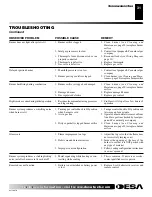
Page 30: ...e B Dirty or partially clogged pilot 5 Thermocouple connection loose at con trol valve 6 Thermocouple damaged 7 Control valve damaged REMEDY 1 Reconnect ignitor cable 2 Free ignitor cable if pinched by any metal or tubing Keep ignitor cable dry 3 Tighten nut holding piezo ignitor Nut is located behind the mounting bracket 4 Replace ignitor cable 5 Replace piezo ignitor 6 Replace pilot assembly 7 R...

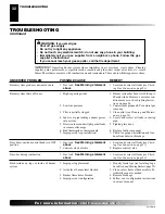
Page 31: ...oved from line Have gas line checked by local pro pane LP or natural gas company 3 Clean burner see Cleaning and Maintenance page 29 or replace burner orifice 1 Adjust the log set so that the flame does not excessively impinge on it 2 Inspect the opening at the base of the burner to see that it is NOT packed with any type of material 3 Follow venting configuration instructions in owner s manual 1 ...

Page 32: ... above 2 Control valve defective 1 Gas leak See Warning statement above 1 Improper log placement 2 Air holes at burner inlet blocked 3 Burner flame holes blocked 4 Improper vent configuration OBSERVED PROBLEM Burner system produces unwanted odors Burner system shuts off in use Gas odor even when control knob is in OFF position Gas odor during combustion Dark residue on logs or inside of burner sys...

Page 33: ...0 lbs 31 8 kg 70 lbs 31 8 kg Shipping 75 lbs 34 kg 75 lbs 34 kg When installed in a model SCIVF PSCIVF series cast iron stove body REPLACEMENT PARTS Note Use only original replacement parts This will protect your warranty coverage for parts replaced under warranty PARTS UNDER WARRANTY Contact authorized dealers of this product If they can not supply original replacement part s call DESA s Technica...

Page 34: ...ormation visit www desatech com 34 TPTH TP TH TPTH TP TH 4 19 20 21 23 26 1 26 4 26 2 26 3 6 24 4 25 4 1 28 28 4 7 8 9 18 10 11 13 12 15 16 17 4 2 3 22 27 14 4 5 22 23 ILLUSTRATED PARTS BREAKDOWN MODELS SDVBND SDVBPD ILLUSTRATED PARTS BREAKDOWN Models SDVBND and SDVBPD ...

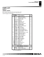
Page 35: ... 20B Hex Head Cap Screw 2 13 NTC 4C Locknut 2 14 105468 02CK Valve Bracket 1 15 104496 01 Valve Natural 1 104496 02 Valve Propane LP 1 16 105486 01 Pilot Assembly Natural 1 105486 02 Pilot Assembly Propane LP 1 17 102445 01 Ignitor Piezo 1 18 107014 01 Center Cast Stove Top Grate 1 19 106036 01 Burner Natural 1 106036 02 Burner Propane LP 1 20 104506 16 Orifice Natural 1 104506 17 Orifice Propane ...

Page 36: ...VF AND PSCIVF SERIES VICTOR HEARTH VH SERIES OXFORD VCIS AND PVCIS SERIES Indicates Color Suffix Designation ILLUSTRATED PARTS BREAKDOWN SCIVF PSCIVF VH VCIS AND PVCIS Series Stove Bodies 5 3 5 5 7 6 7 7 6 7 3 1R 1C 1L 9 8 8 9 2 7 4 7 Oxford Stove Body Victor Hearth Stove Body Amity Stove Body Amity Only Discard Amity Only Discard Discard ...

Page 37: ...e 1 104175 07 104175 07 104175 07 One Leg Porcelain Enamel Red 4 Total Per Stove 1 104175 08 104175 08 104175 08 One Leg Porcelain Enamel Green 4 Total Per Stove 1 104175 09 104175 09 104175 09 One Leg Porcelain Enamel Sand 4 Total Per Stove 1 104175 44 104175 44 104175 44 One Leg Porcelain Enamel Black 4 Total Per Stove 1 6 104176 01 104176 01 104176 01 Leg Leveler bolt M8 x 1 25 55mm Long 4 Tota...

Page 38: ...s Allows burner system to be converted from natural gas to propane LP gas STOVE HEARTH BASE GC10SPA Not Shown Forallmodels Hearthbasestainedoakfinish Requiredwhenstove is placed on carpet Dimensions 4 x 35 3 4 x 30 1 2 H x W x D SERVICE HINTS When Gas Pressure Is Too Low pilot will not stay lit burners will have delayed ignition burner system will not produce specified heat propane LP gas supply m...

Page 39: ...l Completed College Completed Graduate School 13 Age of Purchaser Under 20 20 29 30 39 40 49 50 59 60 or Over 14 Buyer s total annual household income Under 15 000 15 000 to 19 999 20 000 to 34 999 35 000 to 49 999 50 000 to 74 999 75 000 to 99 999 100 000 and Over 15 Store where product was purchased Name ______________________________________ City _______________________ State __________ 16 In c...

Page 40: ...112126 01B For more information visit www desatech com For more information visit www desatech com 40 2701 Industrial Drive P O Box 90004 Bowling Green KY 42102 9004 Postage Required TAPE TAPE ...

Page 41: ...____________________________________________________________ _______________________________________________________________________________________________ _______________________________________________________________________________________________ _______________________________________________________________________________________________ ___________________________________________________...

Page 42: ...iring a defective stove and burner system will be the responsibility of the owner TO THE FULL EXTENT ALLOWED BY THE LAW OF THE JURISDICTION THAT GOVERNS THE SALE OF THE PRODUCT THIS EXPRESS WARRANTY EXCLUDES ANY AND ALL OTHER EXPRESSED WARRANTIES AND LIMITS THE DURATION OF ANY AND ALL IMPLIED WARRANTIES INCLUDING WARRANTIES OF MERCHANTABILITY AND FITNESS FOR A PARTICULAR PURPOSE TO FOUR 4 YEARS ON...

Reviews: