background image

106828-01C

For more information, visit www.desatech.com

For more information, visit www.desatech.com

9

9

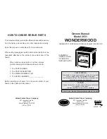
Figure 20 - Control Valve Terminals

To Control Switch

INSTALLATION PRECAUTIONS

Consult local building codes before beginning the installation. Only
a qualified service person should install venting system. The in-
staller must follow these safety rules:

• Wear gloves and safety glasses for protection

• Use extreme caution when using ladders or when on roof tops

• Be aware of electrical wiring locations in walls and ceilings

The following actions will void the warranty on your venting
system:

• Installation of any damaged venting component

• Unauthorized modification of the venting system

• Installation of any component part not manufactured or approved

by DESA

• Installation other than as instructed by these instructions

VENTING INSTALLATION

 WARNING: Read all instructions completely and

thoroughly before attempting installation. Failure to
do so could result in serious injury, property damage,
or loss of life. Operation of improperly installed and
maintained venting system could result in serious
injury, property damage, or loss of life.

NOTICE: Failure to follow these instructions will void
the warranty.

4.

Open lower door panel. The valve is attached to the underside
of the burner system assembly.

5.

Connect one terminal of the wire from ON/OFF switch to the
THTP terminal on the valve. Connect remaining wire terminal
to the TH terminal on the valve. Make sure that the wire termi-
nals are in the positions on the unit as pictured in Figure 20. If
wires are not connected as shown, the ON/OFF switch will
not work.

 WARNING: This gas stove with burner system

and vent assembly must be vented directly to the
outside. The venting system must NEVER be at-
tached to a chimney serving a separate solid fuel
burning appliance.

Your DESA stove with B-vent burner system is approved for use
with any listed gas vent. A listed gas vent is a factory made and listed
system designed, and installed exclusively for removing products of
combustion, excess air, and dilution air resulting from burning fuel
gas. Metal vents, the most common type of vent, employ double
wall construction enclosing an insulating air space. This air space
both helps keep flue gases warm and reduce heat transferred to
nearby combustibles. This appliance is equipped with a safety
control system designed to protect against improper venting of
combustion products.

It is very important that the venting system maintain its balance
between the combustion air intake and the flue gas exhaust. Certain
limitations apply to vent configurations and must be strictly followed.

TYPE B-VENT INSTALLATION
(Listed B-0 or Greater)

Before beginning installation be sure that the overall height and gas
vent size conform to building code requirements. Gas vents extending
through pitched roofs can extend a minimum height of at least 600 mm
(2') higher than any obstruction within 3m (10'). Gas vents extending
through flat roofs are required to extend at least 600 mm (2') above the
roof and at least 600 mm (2') higher than any portion of the building
or adjoining building within 3m (10') of the gas vent.

• In absence of local codes, follow Section 7.0 of the current Na-

tional Fuel Gas Code NFPA 54/ANSI Z223.1 and the Natural
Gas Installation Code 
- vent sizings for Category I systems us-
ing double wall B-1 vent pipe.

• Where the gas vent extends through accessible spaces, it should

be enclosed to avoid personal contact and damage. Enclosure
walls should have a fire rating equal to or greater than the floors
through which the gas vent passes except in single or two-fam-
ily dwellings.

• Situate the gas vent in the structure so that it can be installed

without cutting joists, sills, plates, or major load bearing parti-
tions or members. It is also important to locate the base of the
gas vent as near as possible to the heating appliance.

• This burner system must be properly connected to a venting system.

This burner system is equipped with a vent safety shutoff system.

• Use only vents labeled "FOR EXTERIOR USE" above the

roofline.

• Consult the authority having jurisdiction to select the correct

gas vent diameter. Avoid using a larger than necessary diameter.

CAST IRON STOVE AND B-VENT
BURNER SYSTEM ASSEMBLY

Continued

CAST IRON STOVE AND B-VENT BURNER SYSTEM ASSEMBLY

Installing Rear Cover (Cont.)

VENTING INSTALLATION

Installation Precautions

Type B-Vent Installation

Summary of Contents for SBVBN

Page 1: ...or any other appliance Installation and service must be performed by a qualified installer service agency or the gas supplier IMPORTANT This B vent burner system must be installed into approved DESA c...

Page 2: ...operlyinstalledbyaqualifiedservicepersonwithglass door properly seated and sealed gas leakage can occur Carbon Monoxide Poisoning Early signs of carbon monoxide poisoning resemble the flu with headach...

Page 3: ...als gasoline and other flammable vapor and liquids Do not run burner system where these are used or stored Do not place items such as clothing or decorations on or around stove 12 Do not use this sto...

Page 4: ...low all local codes In the absence to local codes use the current National Fuel GasCode ANSIZ223 1 NFPA54 USA orthecurrentCAN CGA B149 1 or 2 Installation Codes Canada Available from American National...

Page 5: ...uct Identification Label Back Stove Panel CASTIRONSTOVEANDB VENT BURNER SYSTEM ASSEMBLY Pallet Wood Bolted to Bottom of Stove Body Figure 7 Laying Down Stove On Side Front of Stove Unit Top of Stove U...

Page 6: ...or leveling after stove is in normal stand ing position 12 Carefully lift stove back up on its four attached legs 13 Remove 2 bolts from bottom of stove and discard Remove bolt from the top of the sto...

Page 7: ...ure 16 2 Separate bottom cover from rear cover by loosening the 8 mounting screws see Figure 16 3 Align the holes in the top mounting tabs of blower with the holes in wall of rear cover Using the 4 sc...

Page 8: ...al switch has been properly installed to fit against back of burner system in sert after the rear cover assembly has been reinstalled 11 Make sure all wire connections to terminals on blower motor and...

Page 9: ...etal vents the most common type of vent employ double wall construction enclosing an insulating air space This air space both helps keep flue gases warm and reduce heat transferred to nearby combustib...

Page 10: ...Configuration Through Chimney Figure 24 Venting Through a Side Wall Figure 21 Typical B Vent Installation Round Top Storm Collar Flashing Roof Support 25mm 1 Clearance to Combustible Material Firesto...

Page 11: ...t access may be required NOTICE Consult the authority having jurisdiction in your area regarding listed chimney liner venting applications WARNING Operation of improperly installed and maintained vent...

Page 12: ...ge is suspected SeeChecking Gas Connection pages 14 and 15 CAUSES OF SPILLAGE AND CORRECTIVE ACTION Incorrect Vent Sizing If the vent is too small or too short spillage may occur If the vent is too la...

Page 13: ...AND B VENT BURNER SYSTEM INSTALLATION Continued Installation must include an equipment shutoff valve union and plugged1 8 NPTtap LocateNPTtapwithinreachfortestgaugehook up NPT tap must be upstream fr...

Page 14: ...uipment shutoff valve to gas supply Check reconnected fittings for leaks CHECKING GAS CONNECTIONS WARNING Test all gas piping and connections internal and external to unit for leaks after installing o...

Page 15: ...emaining wire terminal to the TH terminal on the valve Make sure that the wire termi nals are in the positions on the unit as pictured in Figure 34 If wires are not connected as shown the switch will...

Page 16: ...ermo stat no outside wall IMPORTANT The wire must not ex ceed 25 feet in length The thermostat should be mounted 54 above the floor in a location where there is good air circulation Avoid heat sources...

Page 17: ...ithout the glass door panel securely in place For replacement part infor mation see Replacement Parts page 26 1 Remove 2 bolts from bottom of stove if still installed and one from the top of stove to...

Page 18: ...ssary to use all of the lava rock provided WARNING Failure to position the parts in accor dance with these diagrams or failure to use only parts specificallyapprovedwiththisburnersystemmayresult in pr...

Page 19: ...the control system and any gas control which has been under water FOR YOUR SAFETY READ BEFORE LIGHTING LIGHTING INSTRUCTIONS 1 STOP Read the safety information above 2 Set ON OFF switch located on re...

Page 20: ...Turns Remote On or Off and Allows You to Choose the Manual Setting Selects Auto Setting Increases Room Temperature in AUTO Mode Locks System to Prevent Accidental Ignition Digital Display Shows Temper...

Page 21: ...GWMT1 WALL MOUNTED THERMOSTAT LighttheburnersystemasinstructedinLightingInstructions on page 19 Set wall thermostat to desired temperature This thermostat has been electronically calibrated at the fac...

Page 22: ...ling Logs Lava Rock and Glowing Embers page 18 to properly replace logs Use a vacuum cleaner to remove any carbon build up on logs Replace log s if broken See Replacement Parts on page 26 Replace embe...

Page 23: ...g enough 3 Equipment shutoff valve not fully open 4 Control valve damaged REMEDY 1 Reconnect ignitor cable 2 Free ignitor cable if pinched by any metal or tubing Keep ignitor cable dry 3 Tighten nut h...

Page 24: ...ation 1 Operate burner until air is removed from line Have gas line checked by local pro pane LP or natural gas company 2 Clean burner see Cleaning and Maintenance page 22 or replace burner orifice 1...

Page 25: ...ent above 2 Control valve defective 1 Gas leak See Warning statement above 1 Improper log placement 2 Air holes at burner inlet blocked 3 Burner flame holes blocked OBSERVED PROBLEM Burner system prod...

Page 26: ...r servicing REPLACEMENT PARTS Note Use only original replacement parts This will protect your warranty coverage for parts replaced under warranty PARTS UNDER WARRANTY Contact authorized dealers of thi...

Page 27: ...pply Pressure 4 5 w c 11 0 w c Thermal Efficiency 70 70 Dimension Inches mm HxWxD Stove and Burner System 27 x 26 1 4 x 20 27 x 26 1 4 x 20 685 8 x 660 4 x 635mm 685 8 x 660 4 x 635mm Carton Insert On...

Page 28: ...more information visit www desatech com 28 ILLUSTRATED PARTS BREAKDOWN MODELS SBVBN C AND SBVBP C 4 4 17 18 19 21 23 1 23 4 23 2 23 3 27 4 22 10 16 11 8 1 25 25 4 13 14 20 20 4 5 3 6 26 2 24 7 12 15...

Page 29: ...l Switch 1 17 106036 01 Burner Natural 1 106036 02 Burner Propane LP 1 18 104506 16 Orifice Natural 1 104506 17 Orifice Propane LP 1 19 14528 Brass Elbow 1 20 901056 01 Brass Elbow 2 21 101628 04 Flex...

Page 30: ...om For more information visit www desatech com 30 ILLUSTRATED PARTS BREAKDOWN AMITY SCIVFC SERIES PSCIVFC SERIES Indicates Color Suffix Designation 2 5 8 7 4 6 5 5 7 1 7 2 5 4 7 3 1R 1C 1L 3 ILLUSTRAT...

Page 31: ...175 05 One Leg Forest Green 4 Total Per Stove 1 104175 06 One Leg Metallic Charcoal 4 Total Per Stove 1 104175 07 One Leg Porcelain Enamel Red 4 Total Per Stove 1 104175 08 One Leg Porcelain Enamel Te...

Page 32: ...L MOUNTED THERMOSTAT CONTROL KIT GWMT1 Not Shown For all models Allows easy wall access to the operation of your burner system This will allow you thermostatic control with the convenience of a wall s...

Page 33: ...Completed College Completed Graduate School 13 Age of Purchaser Under 20 20 29 30 39 40 49 50 59 60 or Over 14 Buyer s total annual household income Under 15 000 15 000 to 19 999 20 000 to 34 999 35...

Page 34: ...106828 01C For more information visit www desatech com For more information visit www desatech com 34 2701 Industrial Drive P O Box 90004 Bowling Green KY 42102 9004 Postage Required TAPE TAPE...

Page 35: ...________________________________________________________ _______________________________________________________________________________________________ _______________________________________________...

Page 36: ...stic cost labor transportation and any and all such other costs related to repairing a defective heater will be the responsibility of the owner TO THE FULL EXTENT ALLOWED BY THE LAW OF THE JURISDICTIO...

Reviews: