background image

111250-01C

For more information, visit www.desatech.com

For more information, visit www.desatech.com

26

OPERATING FIREPLACE

Continued

OPERATING FIREPLACE

Optional Hand-Held Remote Operation

O

FF

PIL

OT

O

N

L

O

IH

ON

OFF

REMO

TE

ON

OFF

Blower Control Knob
(Optional Accessory)

Variable
Control Knob

Selector Switch
in Remote
Position

Gas Control Knob
in ON Position

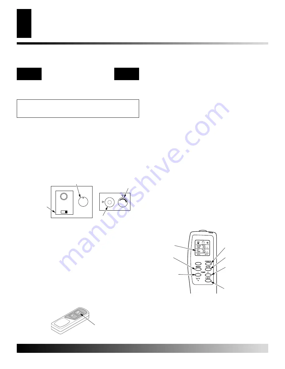
Figure 52 - Setting the Selector Switch, Gas Control Knob, and
Variable Control Knob for Remote Operation

After lighting, let pilot flame burn for about one minute. Turn
control knob to ON position. Adjust flame adjustment knob
anywhere between HI and LO. Slide the selector switch to the
REMOTE position (see Figure 52). 

Note:

 The burner may light

if hand-held remote was on when selector switch was last turned
off. You can now turn the burner on and off with the hand-held
remote control unit.

IMPORTANT:

 Do not leave the selector switch in the REMOTE

or ON position when the pilot is not lit. This will drain the
battery.

ON/OFF SERIES (MODEL GHRCB)

Hold the control button on the hand-held remote until burner
turns on. Hold the control button again until burner turns off
(see Figure 53).

TO LOCK

 press both buttons on hand-held remote control until

light stops flashing. Hand-held remote control is now locked. If
the fire is on it will be turned off automatically. In the locked
state, the light will not light up when any button is pressed.

TO UNLOCK

 press both buttons together on hand-held remote

control until the light stops flashing. The hand-held remote is
now unlocked.

THERMOSTAT SERIES (MODEL GHRCTB)

The hand-held remote can be operated using either the manual
mode (MANU) or thermostatic mode (AUTO) (see Figure 54).
To select Fahrenheit/Centigrade mode display, carefully press
the 

˚

C/

˚

F mode button with the end of a paper clip or similar

blunt object.

Manual Mode

1.

Press the POWER and LOCK buttons together to turn on
the hand-held remote control.

2.

Press the MANU button to turn on the fireplace.

3.

Press the POWER and LOCK buttons together to turn off
the fireplace.

Auto (Thermostatic) Mode

1.

Press the POWER and LOCK buttons together to turn on
the hand-held remote control.

2.

Press AUTO button to select this mode.

3.

Set the desired room temperature by pressing the TEMP +
or - buttons.

4.

Press the POWER and LOCK buttons together to turn off
the fireplace

Note:

 Do not leave the hand-held remote in the AUTO mode

close to the fireplace. The radiant heat from the fireplace will
turn off the fireplace. Ideally, place the hand-held remote in the
center of the room facing towards the fireplace.

Note:

 Do not hold the hand-held remote for a long time. Body

temperature will affect its operation in the AUTO mode.

Safety Features

When away from home for an extended period of time or as a
child safety feature to prevent accidental ignition of the fire-
place, the receiver ON/OFF/REMOTE switch should be in the
OFF position.

Note:


All remote control accessories must be purchased sepa-

rately (see 

Accessories, 

page 37). Follow instructions included

with the remote control.

OPTIONAL HAND-HELD

REMOTE OPERATION

NOTICE: You must light the pilot before using the
hand-held remote control unit. See 

Lighting Instruc-

tions on page 25.

Figure 53 - On/Off Hand-Held Remote Control Unit (GHRCB)

Control Button
Turns Burners
On and Off

Figure 54 - Thermostat Hand-Held Remote Control Unit (GHRCTB)

Turns Hand-Held
Remote On or Off and
Allows You to Choose
the Manual Setting

Selects Auto Setting

Increases Room
Temperature in AUTO
Mode

Locks System to
Prevent Accidental
Ignition

Digital Display
Shows
Temperature and
Settings

Turns Burners
On or Off

Decreases Room
Temperature in
AUTO Mode

Summary of Contents for CTDV36NRA

Page 1: ...rmarket permanently located manufactured mobile home where not prohibited by state or local codes WARNING If the information in this manual is not followed exactly a fire or explosion may result caus ing property damage personal injury or loss of life FOR YOUR SAFETY Donotstoreorusegasolineorotherflammablevapors andliquidsinthevicinityofthisoranyotherappliance Installation and service must be perf...

Page 2: ...nting system Itbringsinfreshairforcombustionthroughtheouterpipeand combustion gases are exhausted through the inner pipe If the glass door assembly and venting pipe are not properly seated connected and sealed carbon monoxide leakage spillage can occur Carbon Monoxide Poisoning Early signs of carbon monoxide poisoning resemble the flu with headaches dizziness or nausea If you have these signs the ...

Page 3: ...s fireplace to cook food or burn paper or other objects 13 Do not use any solid fuels wood coal paper cardboard etc in this fireplace Use only the gas type indicated on fireplace nameplate 14 This appliance when installed must be electrically grounded in accordance with local codes or in the absence of local codes with the National Electrical Code ANSI NFPA 70 or the Ca nadian Electrical Code CSA ...

Page 4: ... location for your fireplace and termination cap When deciding the location of your fireplace follow these rules Do not connect this fireplace venting to a chimney flue serving a separate solid fuel burning fireplace or appliance Due to high temperatures do not locate this fireplace in high traf fic areas windy or drafty areas or near furniture or draperies Proper clearances must be maintained If ...

Page 5: ...ove the fireplace Note Noncombus tible mantels may discolor PRE INSTALLATION PREPARATION Continued NOTICE This fireplace is intended for use as supple mental heat Use this fireplace along with your pri mary heating system Do not install this fireplace as your primary heat source If you have a central heat ing system you may run system s circulating blower while using fireplace This will help circu...

Page 6: ...inlet 72 inches 182 9cm minimum L clearance above paved side walk or a paved driveway located on public property 84 inches 213 3cm minimum M clearance under veranda porch deck 12 inches 30 5cm minimum N clearance above a roof shall extend a minimum of 24 inches 61cm above the highest point when it passes through the roof surface and any other obstruction within a horizontal distance of 18 inches 4...

Page 7: ...y to the outside The venting system must NEVER be attached to a chimney serv ing a separate solid fuel burning appliance Each direct vent gas appliance must use a separate vent system Do not use common vent systems WARNING Vent pipe air space clearances to com bustibles are 1 on all sides except on the horizontal sections which require 2 clearances from the top of the pipe Where the termination ca...

Page 8: ...e the location where the vent pipe assembly will penetrate the outside wall The center of the hole should line up with the center line of the horizontal vent pipe Mark the wall for a 10 x 10 square hole Cut and frame the square hole in the exterior wall where the vent will be terminated If the wall being penetrated is constructed of noncombustible material such as masonry block or concrete a 7 3 4...

Page 9: ... to accommodate standoff Bolt the vent cap to the stand off Apply non hardening mastic around outside edge of stand off Position the standoff cap assembly in the center of the 10 square hole and attach to exterior wall with wood screws pro vided see Figure 11 The siding standoff must sit flush against the exterior fascia material 7 Combustible Exterior Wall Only Slide the wall firestop over the ve...

Page 10: ...mum1 4 riseforevery12 ofruntowardthetermination Figure 13 Typical Horizontal Termination Cap Mounting with Additional Siding Standoff Installed Siding Standoff Screws High Wind Termination Apply Mastic to Outside Edge of Standoff Exterior Wall with Vinyl Siding 10 x 10 Framed Opening Maintain 1 Minimum Air Space Around Outer Pipe When Penetrating a Wall Minimum Pipe Overlap 11 4 Wall Firestop Dire...

Page 11: ...tallation where one foot clearance from ground to termination is possible SNORKEL TERMINATION INSTALLATION Recommended Applications Installations requiring a vertical rise on building exterior Any installation using snorkel termination to achieve one foot above ground Snorkel terminations are available for installations requiring a vertical rise on the exterior of the building If installingsnorkel...

Page 12: ...ace Venting with Two 90 Elbows Vertical V Horizontal H1 Horizontal H1 Horizontal H2 5 min 2 max 6 max 6 min 4 max 12 max 7 min 6 max 18 max 8 min 8 max 20 max 20 max 8 max 20 max Figure 17 Horizontal Termination Configuration for Venting Using Two 90 Elbows VENTING INSTALLATION INSTRUCTIONS Continued VENTING INSTALLATION INSTRUCTIONS Installation Planning Cont 45 Elbow 45 Elbow HORIZONTAL SYSTEM I...

Page 13: ...install firestop above framed hole 2 Assemble the desired lengths of pipe and elbows necessary to reach from the fireplace flue up through the firestop Be sure all pipe and elbow connections are fully twist locked see Fig ure 8 page 8 3 Cut a hole in the roof using the locating hole as a center point Cover any exposed open vent pipes before cutting hole in roof The 10 x10 hole must be measured on ...

Page 14: ...0 Elbow Vertical V Horizontal H 5 min 2 max 6 min 4 max 7 min 6 max 8 min 8 max 20 max 8 max Figure 22 Vertical Venting Configuration Using One 90 Elbow Vertical Round High Wind Termination Shown Note Install restrictor into inner collar of fireplace as shown Venting with Two 90 Elbows Vertical V1 Horizontal H 5 min 6 max 6 min 12 max 7 min 18 max 8 min 20 max Note Vertical V1 Vertical V2 40 max F...

Page 15: ...00 feet Canada When installing this fireplace at an elevation above 2000 feet in the USA you may need to decrease the input rating by changing the existing burner orifice to a smaller size Reduce input 4 for each 1000 feet above sea level Check with your local gas company for proper orifice size identification When installing this fireplace at an elevation above 4500 feet in Canada check with loca...

Page 16: ...Termination Galvanized VT 47 Vertical Round Termination Galvanized ST 47 14 14 Snorkel Termination Galvanized ST 47 36 36 Snorkel Termination Galvanized DESA Venting Accessories Number Description SC 47 Storm Collar Galvanized WF 47 Wall Firestop Galvanized RF 47 6 Roof Flashing 0 to 6 12 Pitch Galvanized RF 47 12 Roof Flashing 6 12 to 12 12 Pitch Galvanized VR 47 Vertical Restrictor Galvanized S ...

Page 17: ...ff by turning knob fully counterclockwise before continuing 10 Peel off the backing paper and stick the supplied wiring dia gram decal on the firebox bottom approximately 12 in front of the blower see Figure 27 Figure 25 Blower Model BK Magnetic Strips Exhaust Port Screw Green Ground Wire Spade Terminals Figure 26 Attaching Speed Control to Firebox Speed Control Control Shaft Locknut Control Knob ...

Page 18: ... speed control secure control shaft with lock nut by pushing and turning lock nut with pliers clockwise un til it is tight against mounting plate Place control knob pro vided on shaft see Figure 26 page 17 7 Check to make sure that the power cord is completely clear of the blower wheel and that there are no other foreign objects in blower wheel Also double check all wire leads and make sure wire r...

Page 19: ...ation must include an equipment shutoff valve union and plugged 1 8 NPT tap Locate NPT tap within reach for test gauge hook up NPT tap must be upstream from fireplace see Figure 31 IMPORTANT Install main gas valve equipment shutoff valve in an accessible location The main gas valve is for turning on or shutting off the gas to the appliance Checkyourbuildingcodesforanyspecialrequirementsforlocating...

Page 20: ...as fireplace or opening main gas valve located on or near gas meter for natural gas fireplace or using compressed air CHECKING GAS CONNECTIONS WARNING Test all gas piping and connections internal and external to unit for leaks after installing or servicing Correct all leaks at once WARNING Never use an open flame to check for a leak Apply a noncorrosive leak detection fluid to all joints Bubbles f...

Page 21: ...al joints for leaks 6 Turn off fireplace see To Turn Off Gas to Appliance page 25 Installing 9 Volt Alkaline Battery in Hand Held Remote Control Unit 1 Remove battery cover on back of remote control unit 2 Attach terminal wires to a 9 volt alkaline battery not included Place battery into the battery housing 3 Replace battery cover onto remote control unit Figure 39 Installing Alkaline Battery in H...

Page 22: ...n and pets away from glass WARNING If fireplace has been running turn off and unplug fireplace Let cool before removing glass door or louvers Spring Latch Hinge Removing Glass Door If replacement of glass is necessary the entire assembly glass and frame must be replaced If glass is broken wear gloves and tape the remaining fragments onto the frame 1 Remove screen assembly by pushing the rod either...

Page 23: ...ING If fireplace has been running turn off and unplug fireplace Let cool before installing brick liner This brick liner kit is optional You may purchase brick liner from your local retailer or see Accessories page 37 CAUTION Always handle brick panels with two hands Do not force brick panels into place Exces sive force will break brick panels 1 Remove top and bottom louvers to allow access to door...

Page 24: ...rock provided WARNING The glass door must be securely in place before running this fireplace Do not run this fireplace if glass is missing or broken NOTICE Do not put lava rock on burner or under burner Placing lava rock on burner will cause perfor mance problems 4 Ember Material Figure 50 Placing Ember Material on Burner Figure 48 Installing Log No 4 5 6 Figure 49 Installing Logs No 5 and No 6 3 ...

Page 25: ...ntrol knob counterclockwise to PILOT 8 Push in gas control knob all the way and hold Immedi ately light the pilot by repeatedly depressing the piezo spark ignitor until a flame appears Continue to hold for about one 1 minute after the pilot is lit Release gas control knob and it will pop back Pilot should remain lit If it goes out repeat steps 5 through 8 If gas control knob does not pop up when r...

Page 26: ...y carefully press the C F mode button with the end of a paper clip or similar blunt object Manual Mode 1 Press the POWER and LOCK buttons together to turn on the hand held remote control 2 Press the MANU button to turn on the fireplace 3 Press the POWER and LOCK buttons together to turn off the fireplace Auto Thermostatic Mode 1 Press the POWER and LOCK buttons together to turn on the hand held re...

Page 27: ... the pilot flame The flame from the pilot burner must extend beyond both the thermocouple and thermopile If you pilot assembly does not meet these requirements turn fireplace off see To Turn Off Gas to Appliance page 25 see Troubleshooting page 29 Thermocouple Thermopile 1 8 Pilot Burner Piezo Ignitor Figure 55 Pilot Assembly 3 8 to 1 2 BURNER FLAME PATTERN Burner flames will be steady not lifting...

Page 28: ...r removing broken glass Do not remove if glass is hot Keep children and pets away from glass WARNING Donotoperatefireplacewiththeglass door removed cracked or broken WARNING Turn off fireplace and let cool before cleaning CAUTION You must keep control areas burners and circulating air passageways of fireplace clean Inspect these areas of fireplace before each use Have fireplace inspected yearly by...

Page 29: ...ty or partially clogged pilot 5 Thermocouple connection loose at con trol valve 6 Thermocouple damaged 7 Control valve damaged REMEDY 1 Reconnect ignitor cable 2 Free ignitor cable if pinched by any metal or tubing Keep ignitor cable dry 3 Tighten nut holding piezo ignitor Nut is located behind the mounting bracket 4 Replace ignitor cable 5 Replace piezo ignitor 6 Replace pilot assembly 7 Replace ...

Page 30: ... minute 2 Operate burner until air is removed from line Have gas line checked by local pro pane LP or natural gas company 3 Clean burner see Cleaning and Mainte nance page 28 or replace burner orifice 1 Adjust the log set so that the flame does not excessively impinge on it 2 Inspect the opening at the base of the burner to see that it is NOT packed with any type of material 1 This is common If no...

Page 31: ...ent installation OBSERVED PROBLEM Fireplace produces unwanted odors Fireplace shuts off in use Gas odor even when control knob is in OFF position Gas odor during combustion Dark residue on logs or inside of fireplace REMEDY 1 Locate and correct all leaks see Check ing Gas Connections page 20 1 Fireplace has been tested for up to 40mph winds However extreme con ditions may occur See Lighting Instru...

Page 32: ...36NRA V T36NRBA V T36PA V T36PBA V T36PRA V T36PRBA and CTDV36NRA ILLUSTRATED PARTS BREAKDOWN V T36NA V T36NBA V T36NRA V T36NRBA V T36PA V T36PBA V T36PRA V T36PRBA AND CTDV36NRA 6 7 20 17 18 10 12 2 11 19 8 22 1 22 4 22 3 22 6 22 5 22 2 1 13 9 21 16 3 14 4 15 5 15 9 10 9 12 9 4 9 5 9 9 9 7 9 3 9 2 9 1 9 13 9 8 9 14 9 11 9 18 9 19 9 15 9 16 9 17 9 6 ...

Page 33: ...r Assembly Natural 1 108074 02 Burner Assembly Propane LP 1 9 1 11102 Screw 8 32 x 3 8 PPH Zinc 2 9 2 11105 Screw 10 x 1 2 Zinc 9 9 3 11179 Screw 10 24 x 1 4 Zinc 4 9 4 11237 Screw Trilab M4 x 8mm 1 9 5 14389 Millivolt Valve Natural 1 14390 Millivolt Valve Propane LP 1 9 6 14492 Piezo Ignitor 1 9 7 14500 Brass Fitting 2 9 8 14508 Flexible Connector 1 9 9 14511 Ignitor SIT Bracket 1 9 10 14528 Bras...

Page 34: ...ier TECHNICAL SERVICE You may have further questions about installation operation or troubleshooting If so contact DESA s Customer Service Depart ment at 1 866 672 6040 When calling please have your model and serial numbers of your heater ready You can also visit DESA s technical service web site at www desatech com REPLACEMENT PARTS Note Use only original replacement parts This will protect your ...

Page 35: ...l Completed College Completed Graduate School 13 Age of Purchaser Under 20 20 29 30 39 40 49 50 59 60 or Over 14 Buyer s total annual household income Under 15 000 15 000 to 19 999 20 000 to 34 999 35 000 to 49 999 50 000 to 74 999 75 000 to 99 999 100 000 and Over 15 Store where product was purchased Name ______________________________________ City _______________________ State __________ 16 In c...

Page 36: ...111250 01C For more information visit www desatech com For more information visit www desatech com 36 2701 Industrial Drive P O Box 90004 Bowling Green KY 42102 9004 Postage Required TAPE TAPE ...

Page 37: ... Kit Platinum FPD36PB Filligree Panel Kit Polished Brass LOUVER TRIM KIT Rolled Louvers Only Not Shown LT36B 36 Rolled Louver Trim Kit Brushed Brass LT36P 36 Rolled Louver Trim Kit Platinum LT36PB 36 Rolled Louver Trim Kit Polished Brass DEFLECTION HOODS Not Shown HD36 36 Hood Black 2 Brow PERIMETER TRIM KIT Not Shown PT36 Perimeter Trim Kit Black PT36B Perimeter Trim Kit Brushed Brass PT36P Perim...

Page 38: ...ransportation and any and all such other costs related to repairing a defective heater will be the responsibility of the owner TO THE FULL EXTENT ALLOWED BY THE LAW OF THE JURISDICTION THAT GOVERNS THE SALE OF THE PRODUCT THIS EXPRESS WARRANTY EXCLUDES ANY AND ALL OTHER EXPRESSED WARRANTIES AND LIMITS THE DURATION OF ANY AND ALL IMPLIED WARRANTIES INCLUDING WARRANTIES OF MERCHANTABILITY AND FITNES...

Reviews: