6
PMA-710AE
1. FRONT PANEL ASSY
(1) Remove the screws.
(2) Cut the wire clamp bands, then loose the style pins.
(3)
Disconnect the connector wires, then remove the screws.
Proceeding : CABINET TOP
FRONT PANEL ASSY
→
View from bottom
Style pin : Loose
cut
CN52
CN53
CN95
CN92
CN94
CN50
CN55
CN51
CN93
CN94
Please refer to "EXPLODED VIEW" for the disassembly method of each P.W.B included in FRONT PANEL ASSY.
Summary of Contents for PMA-710AE
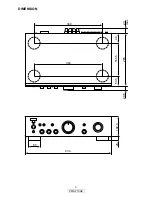
Page 3: ...3 PMA 710AE DIMENSION 344 434 60 102 5 20 265 20 5 23 max 50 5 165 5 49 344...
Page 14: ...14 PMA 710AE MEMO...
Page 15: ...15 PMA 710AE PRINTED WIRING BOARDS MAIN PCB ASSY 1 2 COMPONENT SIDE...
Page 16: ...16 PMA 710AE MAIN PCB ASSY 2 2 FOIL SIDE...
Page 17: ...17 PMA 710AE FRONT PCB ASSY 1 2 COMPONENT SIDE...
Page 18: ...18 PMA 710AE FRONT PCB ASSY 2 2 FOIL SIDE...
Page 25: ...25 PMA 710AE MEMO...
Page 31: ...31 PMA 710AE MEMO...


