10
PMA-710AE
TROUBLE SHOOTING
1. The power can not be turned on. (Power indication LED does not light.)
2. The power turned on, but a sound does not output normally. (Both channels)
2.1.
2.2.
2.3.
Check the insertion of the Power Part.
Check whether power is being supplied to the coil
of the standby transformer (T901).
Power not supplied.
Broken wire in standby trans-
former (T901)
Power supplied.
Malfunction of D941-944, C941
or C943.
Set remains in standby mode with power indicator
LED lit red.
Check each connector.
The connectors are inserted
completely.
Malfunction of RC71 or IC41.
Power indicator LED remains flashing red and
muting mode is not canceled (protection mode is
set).
Check the power amplifier output's offset voltage.
Offset voltage output is 1V or
greater.
Damaged power amplifier cir-
cuit.
No offset voltage is output.
Damaged temperature detec-
tion circuit or protection circuit.
Set operates, but then power indicator LED
flashes red (protection mode is set).
Check the power amplifier output's offset voltage.
Offset voltage output is 1V or
greater.
Damaged power amplifier cir-
cuit.
No offset voltage is output.
Check the bias current.
Summary of Contents for PMA-710AE
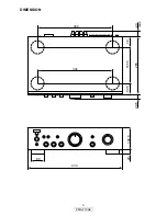
Page 3: ...3 PMA 710AE DIMENSION 344 434 60 102 5 20 265 20 5 23 max 50 5 165 5 49 344...
Page 14: ...14 PMA 710AE MEMO...
Page 15: ...15 PMA 710AE PRINTED WIRING BOARDS MAIN PCB ASSY 1 2 COMPONENT SIDE...
Page 16: ...16 PMA 710AE MAIN PCB ASSY 2 2 FOIL SIDE...
Page 17: ...17 PMA 710AE FRONT PCB ASSY 1 2 COMPONENT SIDE...
Page 18: ...18 PMA 710AE FRONT PCB ASSY 2 2 FOIL SIDE...
Page 25: ...25 PMA 710AE MEMO...
Page 31: ...31 PMA 710AE MEMO...


